Multimode optical fiber for power-over-fiber applications with specific refraction index profile

a technology of refraction index and multimode optical fiber, applied in the direction of optical fiber with graded refractive index core/cladding, optics, etc., can solve the problems of damage to the fiber itself, no consideration is made about a possible input optical power, and hint of tackling, so as to reduce the bending loss, the effect of constant refractive index and cheaper manufacturing process

Active Publication Date: 2019-02-05
PRYSMIAN SPA
View PDF15 Cites 0 Cited by
  • Summary
  • Abstract
  • Description
  • Claims
  • Application Information

AI Technical Summary

Benefits of technology

[0023]The Applicant has realized that the transport of high optical power within the multimode optical fiber can be obtained by selecting a precise combination of parameters for the realization of the optical fiber itself, so that the distance of travel of an electromagnetic radiation having an optical power below the damaging power for the fiber and above a given pre-set power within the fiber can be maximized.
[0024]In particular, the Applicant has found that a predetermined g profile—different from the ideal value of g=2 which is generally the common value of g used for the realization of multimode graded index optical fibers—allows a multimode optical fiber to transport high optical power for distances far greater than 200 m.
[0112]Preferably, the cladding can be homogeneous, i.e. it can have a substantially constant refractive index n2. In some embodiments, the cladding can advantageously have a thickness comprising a region with refractive index depressed with respect to the cladding refractive index n2 and referred to as trench. Such a depressed refractive index can be obtained by fluorine-doping and / or providing holes or voids in the trench, as described, for example, in WO 2008 / 005233, US 2009 / 0185780 and WO2012 / 010212. The presence of said trench can provide a decrease in the bending loss.
[0113]In order to change the refractive index profile of the core according to equation (1), the core should be doped. The cladding preferably remains non-doped (pure silica index profile with a constant refractive index) in order to obtain the desired transmission characteristics, resulting in a cheaper manufacturing process.

Problems solved by technology

Although in U.S. Pat. No. 5,115,486 the problem of transporting high power within an optical fiber has been discussed, there is no hint about tackling the problem of transporting such high optical power as far as possible above a given power threshold within the fiber.
Further, no consideration is made about a possible input optical power which might damage the fiber itself.
Generally, the transport of high power within multimode optical fiber, for example for industrial or medical applications, is limited to distances in the fiber within dozens meters.

Method used


Image

  • Multimode optical fiber for power-over-fiber applications with specific refraction index profile
  • Multimode optical fiber for power-over-fiber applications with specific refraction index profile
  • Multimode optical fiber for power-over-fiber applications with specific refraction index profile

Examples


Embodiment Construction

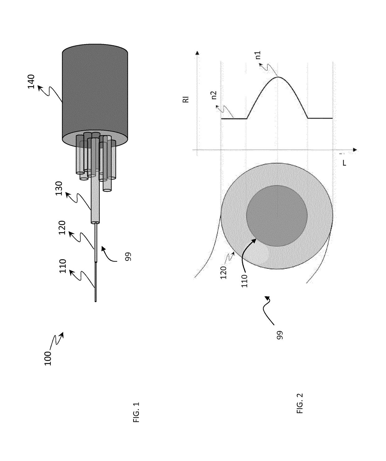
[0140]As shown in FIG. 1, an optical cable 100 for the transmission of “high” power and preferably also of data including a multimode optical fiber 99 is depicted.

[0141]The multimode optical fiber 99 of the invention may not be part of an optical cable but can also be used as a single fiber.

[0142]The optical fiber 99 includes a core 110 and a cladding 120 surrounded by one or more coating layers 130 for protection. The optical cable 100 may include a plurality of optical fibers 99 surrounded by an outer sheath 140 for protection from the external environment.

[0143]FIG. 11 shows an example of application of the optical fiber 99 in a power over fiber application. A system 200 includes three parts: an optical power source OPS comprising a high power laser diode HPLD, a laser diode controller LDC and an optical receiver RX, a remote unit RU (containing a sensor S, a photovoltaic converter PV, a Fabry Perot semiconductor laser FPLD and a converter and driver circuitry FM) and fibers FO r...


PUM


Abstract

A multimode optical fiber for continuous transmission of electromagnetic radiation at high power, wherein the fiber defines a fiber axis and includes a core and a cladding surrounding the core, and wherein the multimode optical fiber is a multimode graded-index fiber, the refraction index profile in the fiber essentially following formula (1):n⁡(r)={n1⁡[1-2⁢(ra)g⁢Δ]1⁢ / ⁢2,r<an2,r>a(1)Δ=n12-n222⁢n12(A)NA=n12-n22(B)where Δ is formula (A), r is the distance from the fiber axis, n(r) is the nominal refractive index as a function of distance from the fiber axis, n1 is the nominal refractive index on the axis of the fiber, n2 is the refractive index of the cladding, a is the core radius, and g is a parameter that defines the shape of the profile, where the core diameter 2a is between 90 UM and 190 μM, the parameter g is between 1.2 and 1.8, and the numerical aperture (NA) of the fiber, formula (B), is between 0.2 and 0.3.

Description

CROSS REFERENCE TO RELATED APPLICATION[0001]This application is a national phase application based on PCT / EP2014 / 074106, filed Nov. 7, 2014, the content of which is incorporated herein by reference.BACKGROUND OF THE INVENTIONField of the Invention[0002]The present invention relates to a multimode optical fiber for transmission of high power over long distances. It refers also to a method for the transmission of high optical power over long distances.Description of the Related Art[0003]In standard fashion, an optical fibre is composed of an optical core the function of which is to transmit an optical signal, and an outer optical cladding the function of which is to confine the optical signal within the core. To this end, the refractive indices of the core (ncore) and the cladding (ncladding) are such that ncore>ncladding.[0004]The refractive index profile denotes the graph of the function which associates the refractive index with the radius of the optical fibre. In standard fashi...

Claims


Application Information

Patent Timeline
Patent Type & Authority Patents(United States)
IPC IPC(8): G02B6/028G02B6/42
CPCG02B6/4296G02B6/0288
Inventor VIEIRA DA SILVA, JOAO CARLOSSP NOLA DE SOUZA, EVANDRO LEE ANDERSONGARCIA, VALERIAROSOLEM, JOAO BATISTAFLORIDIA, CLAUDIOSANCHES, MARCOS ANTONIO BRANDA
Owner PRYSMIAN SPA
Why Eureka
Try Eureka