Pivoting tube brush

a tube brush and rotating technology, applied in the field of rotating tube brushes, can solve the problems of reducing the efficiency of surface area heat transfer, affecting the performance of the machine, and requiring sufficient mass (weight) to withstand, so as to reduce the compressive force of the tape, minimize friction resistance, and improve the effect of tube cleaning operations

Active Publication Date: 2019-01-15
CROSSFORD INT
View PDF24 Cites 1 Cited by
  • Summary
  • Abstract
  • Description
  • Claims
  • Application Information

AI Technical Summary

Benefits of technology

[0005]Pivoting and / or rotating tube brushes may be utilized to provide advantages in tube cleaning operations. Fire-tube cleaners according to embodiments described herein utilize lightweight, high strength components to propel a unique easy-push, clean on return stroke brush for tube cleaning. Brush design minimizes friction resistance on the forward stroke of the cleaning cycle, thereby substantially reducing compressive force on the tape pushing the brush and eliminating tendency of tape to collapse, buckle, or bind within a tube. On the return cleaning stroke the tape is in constant tension and can easily handle the forces involved. A preferred embodiment is designed for modern package boilers usually having tubes of maximum length of sixteen (16) feet and of outside diameter of two inches (2″) to two and one half inches (2½″).
[0007]The machine may also or alternatively include a distance monitor on both sides of the machine, a centrally located rear-mounted operating switch, and a main drive-train of motor, gearbox, clutch, and final drive located within the machine protecting the operator from moving parts and hot (e.g., one hundred and eighty degrees Fahrenheit (180° F.)) exposed drive motor. The machine allows for quick change of steel tape without the need for machine disassembly.

Problems solved by technology

In operation, surface area heat transfer efficiency is diminished by buildup on the fire-tube interior surfaces by products of corrosion, oxidation, soot, and chemical reactions.
Fire-tube boiler cleaning machines are available for tube cleaning, however, such machines are very heavy and hard to use in tight spaces or on elevated catwalks, platforms, or scaffolding.
Additionally, the machine needs sufficient mass (weight) to withstand the high loads developed on the brush forward stroke.

Method used


Image

  • Pivoting tube brush
  • Pivoting tube brush
  • Pivoting tube brush

Examples


Embodiment Construction

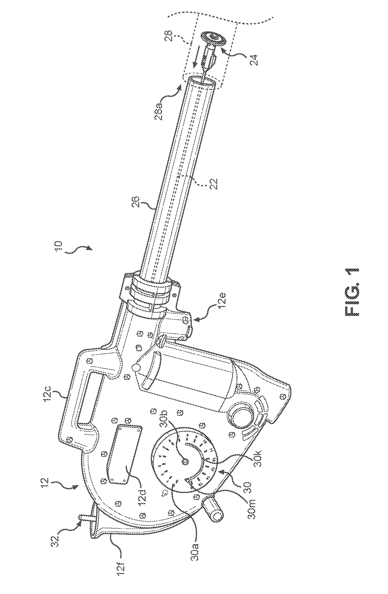
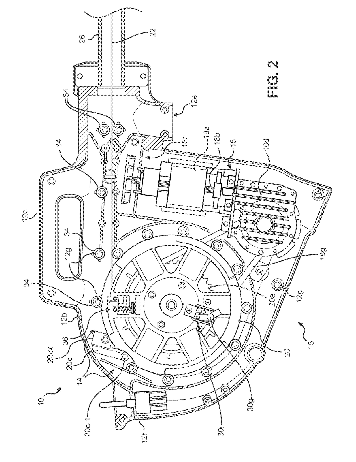
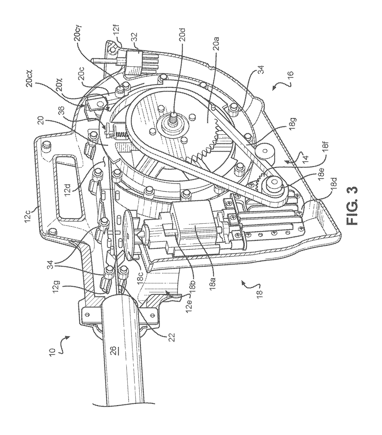
[0028]Referring to FIG. 1, FIG. 2, and FIG. 3 of the drawings, a fire-tube cleaning machine 10 includes housing 12 defined by confronting shell members 12a-b defining an interior space 14 for placement of cleaner operating components 16 including drive-train 18 and tape reel 20 with drum drive gear 20a. The housing further includes carry handle 12c, cover plate 12d for access to tape anchor 36 (also shown in FIG. 6 and FIG. 7), vacuum connection 12e, and cleaner switch console 12f. The shell members 12a-b are secured to each other by suitable fasteners (not shown) at multiple locations 12g.

[0029]A tape 22 and brush and / or brush assembly 24 may be housed in a deployment member in the form of a tape outlet barrel 26 that extends from the housing 12 for insertion into individual fire-tubes 28 so as to position tape 22 and brush assembly 24 at tube entry 28a. The tape outlet barrel 26 serves as a vacuum conduit for carrying dislodged soot from each tube 28 to a vacuum source (not shown...


PUM


Abstract

Pivoting brush heads and associated machines in which cleaning of interior tube surfaces occurs by a forward non-cleaning pass of a pivoting brush head through a tube followed by a reverse cleaning pass where the pivoting brush head engages and cleans the interior surface. The pivoting brush head has a first position for the forward pass producing minimum engagement of interior tube surfaces, and a second position for the reverse pass of full cleaning engagement with the interior tube surfaces.

Description

CROSS-REFERENCE TO RELATED APPLICATIONS[0001]The present application is a Continuation-in-Part (CiP) of, and claims benefit and priority to, U.S. patent application Ser. No. 14 / 939,188 filed Nov. 12, 2015 and titled “FIRE-TUBE BOILER CLEANER”, which issued as U.S. Pat. No. 9,517,496 on Dec. 13, 2016 and which itself claims benefit and priority to U.S. Provisional Patent Application No. 62 / 122,209 filed on Oct. 14, 2014, the entirety of each of which is hereby incorporated by reference herein.BACKGROUND[0002]Embodiments disclosed herein generally relate to pivoting tube brushes, such as may be utilized in tube cleaning operations. In some embodiments, a pivoting tube brush may be utilized in fire-tube boilers and provide solutions to the problem of cleaning the interior surface of fire-tubes with a lighter weight, easier to use machine.[0003]The general construction of a fire-tube boiler is a tank of water penetrated by tubes that carry the hot flue gases from the boiler's combustion...

Claims


Application Information

Patent Timeline
Patent Type & Authority Patents(United States)
IPC IPC(8): B08B9/043F28G15/04F28G1/02A46B13/02B08B9/045F23J3/02F28G1/10F28G15/02
CPCB08B9/0436A46B13/02B08B9/043B08B9/045F28G1/02F28G1/10F28G15/02F28G15/04F23J3/023A46B2200/3013
Inventor KANE, TIMOTHY J.CRUZ, GEORGEWALSH, DAVID L.
Owner CROSSFORD INT
Why Eureka
Try Eureka