Handheld forcible entry device

Inactive Publication Date: 2019-01-01
THAW RICHARD E
View PDF11 Cites 4 Cited by
  • Summary
  • Abstract
  • Description
  • Claims
  • Application Information

AI Technical Summary

Benefits of technology

The invention is a small and powerful door opener that can be easily operated in different directions and is much lighter and compact than other options. It requires less force from the user and is more efficient than hydraulic and pneumatic devices.

Problems solved by technology

The manual tools described above are useful for helping the firefighters and law enforcement agents to open weak doors, which can be opened using a regular lever or slamming force, but they are useless for opening strong doors.
Instead, the hydraulic devices mentioned above are useful for opening strong doors, however they present the following drawbacks:Hydraulic units create major problems by usually blowing out O-ring seals.
Major leaks of oil create a dangerous spreading of toxic chemicals to the environment as well as the emission of fumes into the air.
Furthermore, an extreme explosive surge is also created when seals are blown under pressure;Secondary cylinders and hoses are required;Hydraulics cannot be inverted with usage;In most cases the door is ruined after it is opened;Because of the internal fluids used in its hydraulic circuit, it cannot operate under extreme weather conditions; andThey require excessive regular maintenance when is not being used.
These are similar to the hydraulic ones, with the following drawbacks:Limited time use;Require filtering of air;Difficult to control the movement of components using air;Pressurized gas being extremely dangerous for use in hot or cold environments;Constant and heavy maintenance; andHeavy carrying accessory chargers.

Method used


Image

  • Handheld forcible entry device
  • Handheld forcible entry device
  • Handheld forcible entry device

Examples


Embodiment Construction

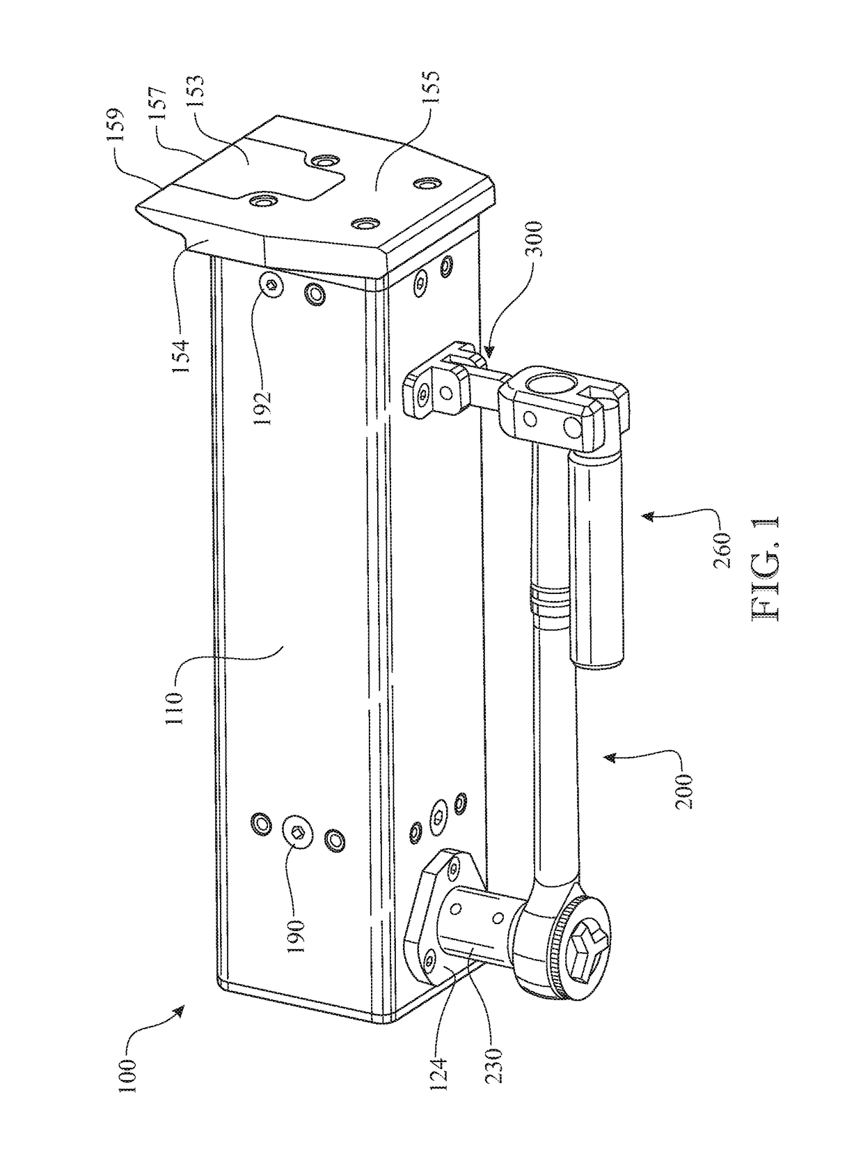
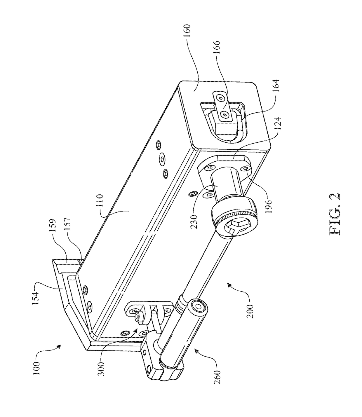
[0102]Detailed embodiments of the present invention are disclosed herein. It will be understood that the disclosed embodiments are merely exemplary of the invention that may be embodied in various and alternative forms. The figures are not necessarily to scale, and some features may be exaggerated or minimized to show details of particular embodiments, features, or elements. Specific structural and functional details, dimensions, or shapes disclosed herein are not limiting but serve as a basis for the claims and for teaching a person of ordinary skill in the art the described and claimed features of embodiments of the present invention. The following detailed description is merely exemplary in nature and is not intended to limit the described embodiments or the application and uses of the described embodiments. As used herein, the word “exemplary” or “illustrative” means “serving as an example, instance, or illustration.” Any implementation described herein as “exemplary” or “illust...


PUM


Abstract

A handheld forcible entry device includes a tubular housing. A torque-input drive shaft is rotationally assembled to the housing, wherein the input shaft rotates about an axis perpendicular to a longitudinal axis of the housing. A helical pressure applicating lead screw is rotationally assembled to the housing, wherein the lead screw rotates about an axis parallel to the housing longitudinal axis. The input shaft and lead screw are rotationally synchronized by a gear assembly. A pressure applicator is threadably engaged with a helical threaded segment integrated in the lead screw. Rotation of the threading advances or retracts the pressure applicator from a stationary wedge plate. The separation of the pressure applicator and the stationary wedge plate separates a locked member from the associated frame, thus forcibly opening the locked member. The input shaft can be operated using a manually applied rotation or power applied rotation.

Description

CROSS REFERENCE TO RELATED APPLICATIONS[0001]This application is a Continuation-In-Part claiming the benefit of United States Non-Provisional Utility patent application Ser. No. 13 / 943,563, filed on Jul. 16, 2013, which in turn is a Continuation-In-Part claiming the benefit of United States Non-Provisional Utility patent application Ser. No. 12 / 786,630, filed on May 25, 2010 and issued as U.S. Pat. No. 8,485,508 on Jul. 16, 2013, which claims the benefit of U.S. Provisional Patent Application Ser. No. 61 / 181,537, filed on May 27, 2009, all of which are incorporated herein in their entireties.FIELD OF THE INVENTION[0002]This invention relates generally to a handheld, mechanical or powered locked door opening device, light in weight and operable in any orientation, for generating a substantial door-opening force. More particularly, the locked door-opening device is capable of providing a set of useful features for emergency personnel using a simple portable device.DESCRIPTION OF THE P...

Claims


Application Information

Patent Timeline
IPC IPC(8): B23Q3/06B66F11/00E05B19/20A62B3/00
CPCB66F11/00A62B3/005E05B19/20B66F15/00
Inventor THAW, RICHARD E.
Owner THAW RICHARD E
Why Eureka
Try Eureka