Eureka AIR delivers breakthrough ideas for toughest innovation challenges, trusted by R&D personnel around the world.

DC/DC converter for high voltage applications with input voltage boost, input capacitor discharge and output capacitor compensation modes

a converter and high-voltage technology, applied in the direction of electric variable regulation, process and machine control, instruments, etc., can solve the problem that the single-stage converter is generally unable to provide wide regulation without compromising efficiency requirements, and achieve the effect of expanding the operating rang

Active Publication Date: 2018-12-18
BEL POWER SOLUTIONS INC
View PDF3 Cites 4 Cited by
  • Summary
  • Abstract
  • Description
  • Claims
  • Application Information

AI Technical Summary

Benefits of technology

The patent describes a DC / DC converter that can regulate its output voltage within a narrow range during normal operation, but can also change its range quickly when needed. This is made possible by using a dual stage topology, which includes an isolated DC / DC stage and a synchronous booster stage. The booster stage is designed to operate in two modes depending on the input voltage: a bypass mode when the input voltage is within a certain range, and a boost mode when the input voltage is below a specific level. This allows the converter to extend its input voltage range and maintain high efficiency.

Problems solved by technology

As previously discussed, a single stage converter is generally unable to provide wide regulation without compromising efficiency requirements.

Method used


Image

  • DC/DC converter for high voltage applications with input voltage boost, input capacitor discharge and output capacitor compensation modes
  • DC/DC converter for high voltage applications with input voltage boost, input capacitor discharge and output capacitor compensation modes
  • DC/DC converter for high voltage applications with input voltage boost, input capacitor discharge and output capacitor compensation modes

Examples


Embodiment Construction

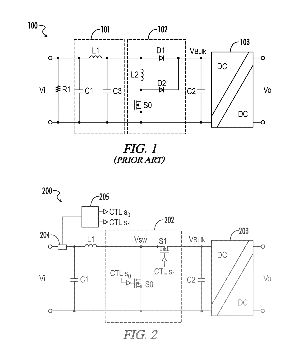
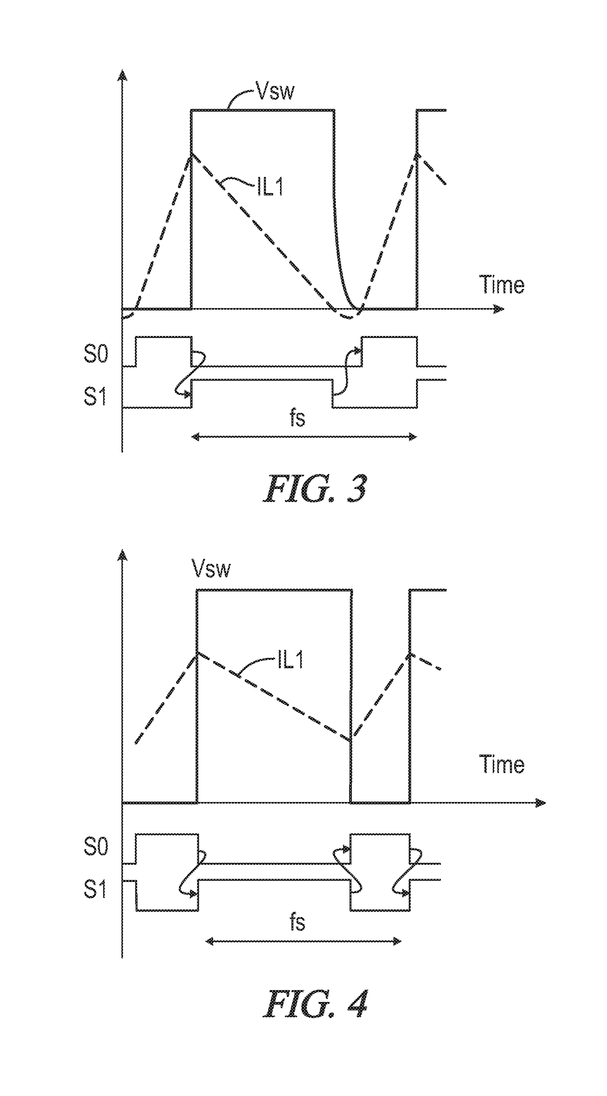
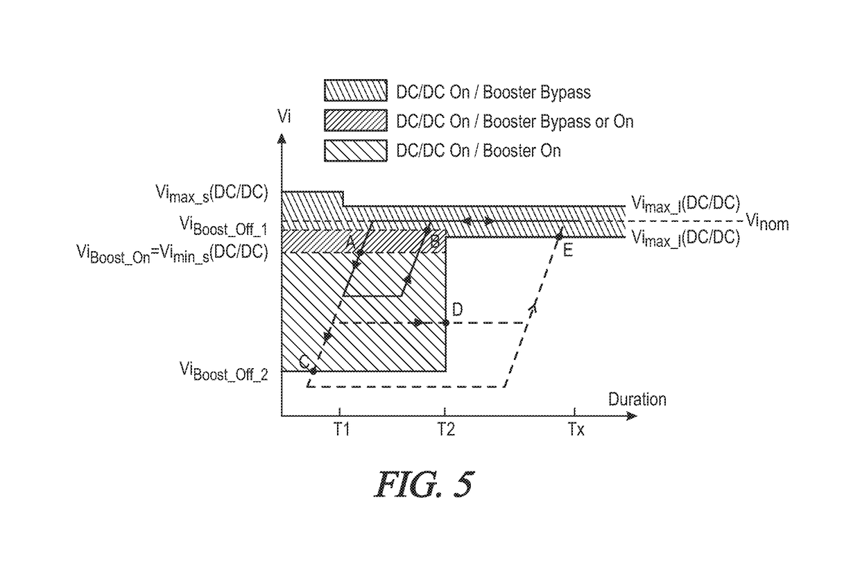
[0027]Referring generally to FIGS. 2-5, various exemplary embodiments of an invention may now be described in detail. Where the various figures may describe embodiments sharing various common elements and features with other embodiments, similar elements and features are given the same reference numerals and redundant description thereof may be omitted below.

[0028]Referring initially to FIG. 2, a switching converter 200 as disclosed herein includes an input power source Vi, and a synchronous boost converter 202 (a booster stage with an active rectification switch S1) in front of an isolated DC / DC converter 203. A controller 205 is configured to generate control signals CTL_S0 and CTL_S1 for driving respective first and second switching elements S0 and S1 in the booster stage 202. During normal operation when the input voltage Vi is within a narrow input voltage range, the booster stage 202 may be bypassed by turning off first switching element S0 and turning on second switching elem...


PUM


Abstract

A DC / DC converter is provided for operation within a narrow voltage range during normal conditions, while allowing for a wider input voltage range for short periods of time. A first switch is coupled across first and second input terminals, and a capacitor is coupled in parallel with the first switch and across the input terminals. A second switch is coupled in series with the first input terminal and between the first switch and the capacitor. Operation of the switches is regulated in accordance with a bypass mode of operation when received input power is within a defined range, and a boost mode of operation when received input power is less than a threshold value, wherein the received input power is boosted to a bulk output power within the defined range. Boost operations may in various embodiments be provided via, for example, a critical conduction scheme or continuous conduction scheme.

Description

[0001]A portion of the disclosure of this patent document contains material that is subject to copyright protection. The copyright owner has no objection to the reproduction of the patent document or the patent disclosure, as it appears in the U.S. Patent and Trademark Office patent file or records, but otherwise reserves all copyright rights whatsoever.CROSS-REFERENCES TO RELATED APPLICATIONS[0002]This application claims benefit of U.S. Provisional Patent Application No. 62 / 256,227, filed Nov. 17, 2015, and which is hereby incorporated by reference.STATEMENT REGARDING FEDERALLY SPONSORED RESEARCH OR DEVELOPMENT[0003]Not ApplicableREFERENCE TO SEQUENCE LISTING OR COMPUTER PROGRAM LISTING APPENDIX[0004]Not ApplicableBACKGROUND OF THE INVENTION[0005]The present invention relates generally to DC-DC power converters. More particularly, this invention pertains to DC-DC converters optimized for high voltage applications.[0006]Large data centers can host thousands of servers consuming sign...

Claims


Application Information

Patent Timeline
Patent Type & Authority Patents(United States)
IPC IPC(8): H02M3/158H02M1/08H02M1/00
CPCH02M3/158H02M1/08H02M2001/0009H02M3/156H02M3/1588Y02B70/10H02M1/0022H02M1/322H02M1/0009
Inventor CINAGROSSI, NICOLAFENO, IVANCHAPUIS, ALAIN
Owner BEL POWER SOLUTIONS INC
Why Eureka
Eureka Blog
Learn More