
Marine-environment, emergency-egress system and method

a technology of emergency exit and marine environment, applied in the field of emergency exit system, can solve problems such as unpractical conventional exit, affecting operation and safety, and the need of riders, and achieve the effect of increasing tension and overcoming the resistance of backward movemen

Inactive Publication Date: 2018-12-11
ZIPHLDG
View PDF67 Cites 2 Cited by
  • Summary
  • Abstract
  • Description
  • Claims
  • Application Information

AI Technical Summary

Benefits of technology

[0015]The procedure of operation is sufficiently simplified that there is comparatively little to remember. Thus, a simple process, straightforward training, and riders may move quickly in an emergency situation to a launch deck, load into a seat or harness, launch when ready, and travel in close proximity. Trolleys may run independently, yet may create a virtual train of trolleys running in close proximity or even touching.
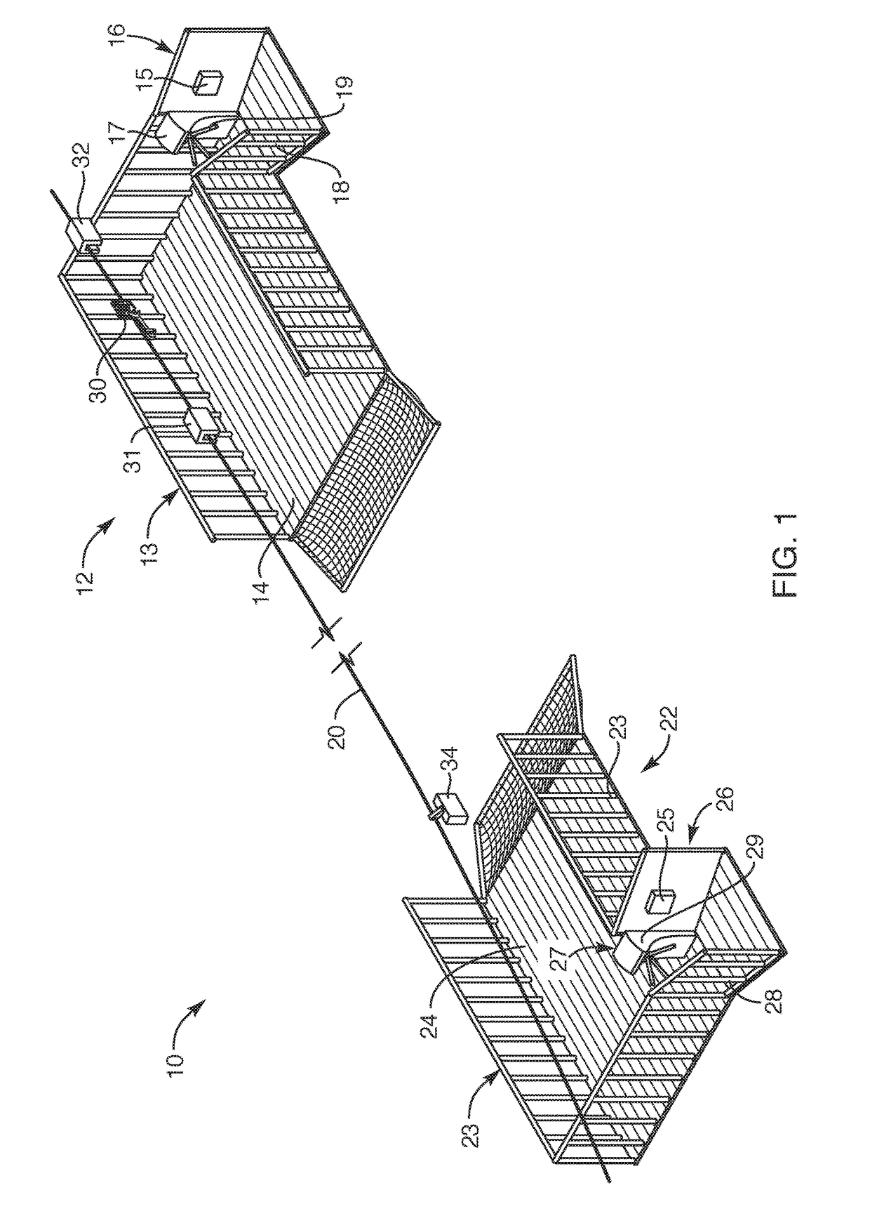
[0016]In certain embodiments, a track line and launch station may be associated with an off-shore platform, such as an off-shore drilling rig or an off-shore petroleum facility. In such an embodiment, trolleys in accordance with the invention may be stabilized so the presence of multiple riders in close proximity to one another does not load the track line. In this way, individuals may load and launch at will, leaving the proper angle of the track line catenary unaffected by the weight of the riders waiting to launch onto the track line toward safety at the lower end thereof.
[0017]The lower end may be anchored to any number of potential marine fixtures including lifeboats, ships, support tenders, tugs, other platform structures, a sea anchor, a sea-floor anchor such as is used on ships conventionally, or to any suitable part of a ship from railing, to bollard, to cleat, anchor chain, cam cleat, or the like. A take-up system at the destination or remote location securing the lower end of the track line may assure length and tension control.
[0019]Meanwhile, a boat itself may serve as an anchor. Such a boat may be provided with a sea anchor. A sea anchor may be pivoting panels that swing out from a boat to resist moving backward with force from a track line. It may be a large parachute-like affair that fills with sea water, and provides tremendous resistance against movement backward.
[0020]In some embodiments, a small watercraft may draw a sea anchor forward, with the sea anchor opening and providing an impulse load any time a rider launches on the track line, and thus provides more tension on the sea anchor than the watercraft itself could support. In this way, the watercraft can continue to draw a sea anchor away from a platform in an emergency, but its own horsepower need not be entirely responsible to hold the substantial tension loads of riders launching down the track line.
[0022]For example, a small boat can draw the track line from an off-shore rig out to a buoy at some distance away. A boat or offshore rig may carry a tensioning device to take up slack. Meanwhile, the boat may connect to the buoy, or connect the track line to the buoy. In this way, an anchor on the sea floor may tether the buoy in place. The tensioning or take-ups system on the rig (platform) or in a small boat that delivers the track line to the buoy may provide regulation of tension, length, and therefore height of the track line above the surface of the sea.

Problems solved by technology

Frequency of use, rider ability, panic, skill, comfort with speed, or the like, and the presence of multiple riders accessing, launching, and riding seats simultaneously, create risks affecting operation and safety.
This creates problems for riders needing to stage loading and launching from a pre-determined height of a deck structure.
What is needed is to rapidly load and carry away workers from a location that has suddenly become dangerous, where time is of the essence, conventional exit is not practical, and personnel may not be available to assist.

Method used


Image

  • Marine-environment, emergency-egress system and method
  • Marine-environment, emergency-egress system and method
  • Marine-environment, emergency-egress system and method

Examples


Embodiment Construction

[0066]It will be readily understood that the components of the present invention, as generally described and illustrated in the drawings herein, could be arranged and designed in a wide variety of different configurations. Thus, the following more detailed description of the embodiments of the system and method of the present invention, as represented in the drawings, is not intended to limit the scope of the invention, as claimed, but is merely representative of various embodiments of the invention. The illustrated embodiments of the invention will be best understood by reference to the drawings, wherein like parts are designated by like numerals throughout.

[0067]A zip line may extend as a catenary, as defined in the engineering art. The term “catenary” is understood by repair to any textbook on structural mechanics or engineering nomenclature. The catenary extends freely between end supports. It may suspend from an upper anchor point to a lower anchor point, the decline of the lin...


PUM


Abstract

Emergency egress systems carry multiple riders simultaneously accessing a zip line (catenary) from higher, accessible, working locations to lower, safer areas in a marine environment. Hangers above the track line suspend trolleys to avoid weighting the catenary unduly at the high end, which might otherwise alter (reduce) clearance distances and safety of riders above a launch platform (deck). Catenary shape is controlled against approaching the launch deck by sequencing the release from the hangers of each trolley to roll along the catenary with its own rider. Track line systems installed may be left undeployed indefinitely. Deployment of a track line will typically be fully effected at the time of egress, adding time but eliminating permanent obstructions that would result if a permanent deployment of track lines were undertaken. Terminal ends are anchored and configured to accommodate workers arriving after escape.

Description

RELATED APPLICATIONS[0001]This application: is a continuation in part of U.S. patent application Ser. No. 15 / 441,101, filed Feb. 23, 2017; and is a continuation in part of U.S. patent application Ser. No. 15 / 354,866, filed Nov. 17, 2016, which claims the benefit of Provisional Patent Application Ser. No. 62 / 257,610, filed Nov. 19, 2015; and is a continuation in part of co-pending U.S. patent application Ser. No. 14 / 923,708, filed Oct. 27, 2015; all of which are hereby incorporated by reference. This application also incorporates herein by reference the following applications and patents: U.S. patent application Ser. No. 14 / 451,932, filed Aug. 5, 2014; U.S. patent application Ser. No. 14 / 711,465, filed May 13, 2015; U.S. Provisional Patent Application Ser. No. 62 / 058,544, filed Oct. 1, 2014; and U.S. patent application Ser. No. 14 / 923,708, filed Oct. 27, 2015. Moreover, this application hereby incorporates herein by reference U.S. Pat. No. 7,637,213, issued Dec. 29, 2009; U.S. Pat. N...

Claims


Application Information

Patent Timeline
Patent Type & Authority Patents(United States)
IPC IPC(8): B61B7/00F16D63/00A62B1/00A63G21/20A63G21/22B61H9/02B61B12/00B61B12/02A62B1/20G06K7/00
CPCB61B7/00A62B1/00A63G21/20A63G21/22B61B12/002B61B12/028B61H9/02F16D63/008B61B12/007G06K7/0004A62B1/20
Inventor CYLVICK, ERIC S.
Owner ZIPHLDG
Learn More