
RFID scheme in harsh environments

a technology of harsh environments and rfid sensors, applied in the field of rfid sensors in harsh environments, can solve problems such as limit the use of rfid sensors

Active Publication Date: 2018-11-27
PHASEIV ENG INC
View PDF2 Cites 29 Cited by
  • Summary
  • Abstract
  • Description
  • Claims
  • Application Information

AI Technical Summary

Benefits of technology

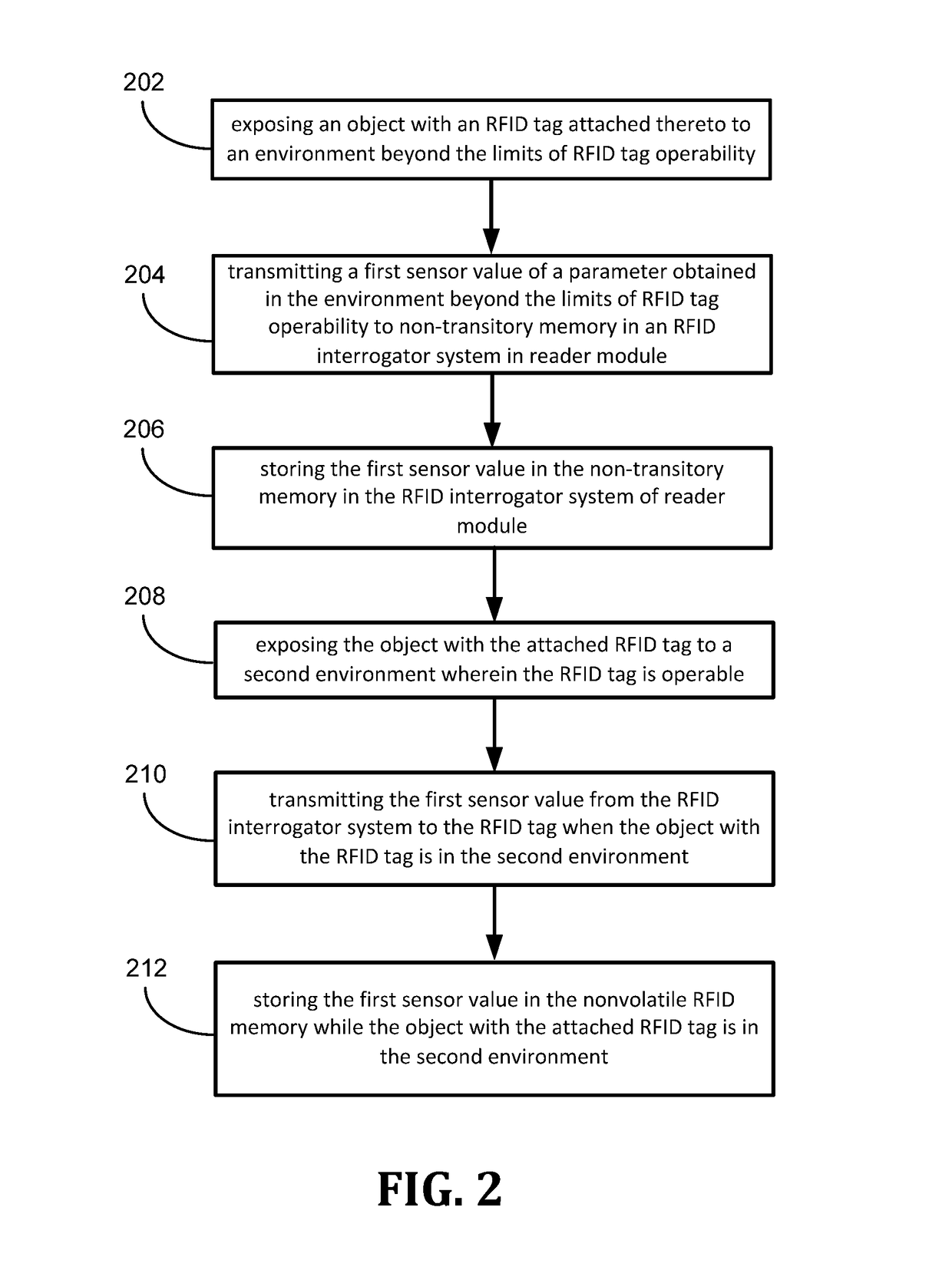
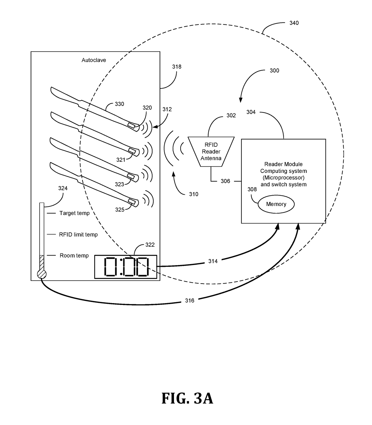
The present invention relates to a system and method for recording parameters to RFID sensors affixed to objects exposed to extreme environments that are beyond the operability of the RFID sensors. The RFID system includes an RFID tag with nonvolatile RFID memory and an RFID interrogator system including a microprocessor, sensor reader, real-time clock, timer, non-volatile interrogator memory and an RFID antenna. The non-volatile interrogator memory contains a value obtained from the sensor during a first environment that renders the RFID tag inoperable, and only after the RFID tag is placed in a second environment where it is operable. The technology allows for the collection and storage of data in the nonvolatile memory of the RFID interrogator system, and the transmission of the data to the RFID tag in a secure and efficient manner. This invention improves the reliability and durability of RFID-based sensing systems in extreme environments, such as high temperatures or high levels of radiation.

Problems solved by technology

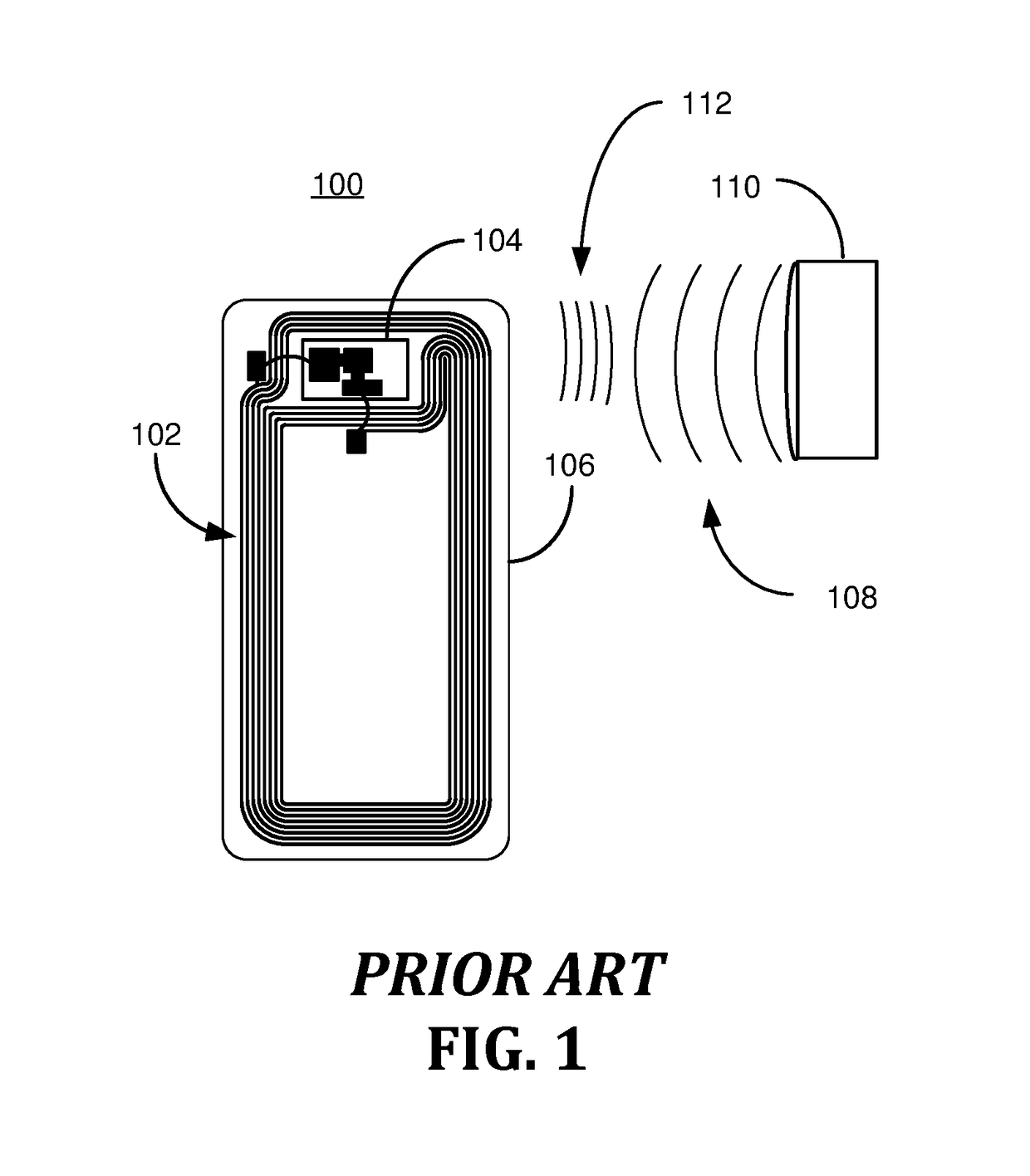
Special RFID tags are placed on books and expensive tools.
There are, however, limits to the uses of RFID sensors.
One such limit includes extreme environmental conditions, such as elevated temperatures, wherein an RFID sensor is dysfunctional or simply inoperable.

Method used


Image

  • RFID scheme in harsh environments
  • RFID scheme in harsh environments
  • RFID scheme in harsh environments

Examples


Embodiment Construction

[0017]Initially, this disclosure is by way of example only, not by limitation. Thus, although the instrumentalities described herein are for the convenience of explanation, shown and described with respect to exemplary embodiments, it will be appreciated that the principles herein may be applied equally to various RFID tags exposed to a variety of environments that exceed operability of RFID tags. In what follows, similar or identical structures may be identified using identical callouts.

[0018]In certain instances, object / s, such as a tool, may intentionally or unintentionally be exposed to extreme environments momentarily or for prolonged periods of time. For purposes of record keeping, it may be desirable to record data associated with the object / s in the extreme environment. An extreme environment can be an elevated temperature or extreme cold or something undergoing high pressure or accelerations, just to name several examples. Extreme environments as used in this disclosure is ...


PUM


Abstract

A method for using an RFID tag to retain information of an environment, such as high temperature, that is beyond the operable limits of the RFID tag. The method generally comprises providing an RFID tag that has nonvolatile RFID memory that can communicate with an RFID interrogator system. Exposing the RFID tag to a first environment (such as a high temperature) that renders the RFID tag inoperable. Collecting a first sensor value of the first environment and storing the first sensor value in nonvolatile memory accessible by the RFID interrogation system. Later, exposing the RFID tag and the sensor to a second environment that renders the RFID tag operable (such as room temperature). Wirelessly transmitting the first sensor value to the RFID tag via the RFID interrogator system while the first sensor is in the second environment, and storing the first sensor value in the nonvolatile RFID memory while the RFID tag is in the second environment.

Description

CROSS-REFERENCE TO RELATED APPLICATIONS[0001]This application is a non-provisional application which claims priority to and the benefit of U.S. Provisional Patent Application Ser. No. 62 / 407,310, entitled RFID SCHEME IN HARSH ENVIRONMENTS filed Oct. 12, 2016, the entire disclosure of which is hereby incorporated by reference.FIELD OF THE INVENTION[0002]The present invention relates generally to systems and methods of recording parameters to memory in RFID tags affixed to objects exposed to extreme environments that are beyond operability of the RFID tags.DESCRIPTION OF RELATED ART[0003]Radio Frequency IDentification (RFID) systems are used in libraries and retail stores like Home Depot. Special RFID tags are placed on books and expensive tools. When the book or tool passes by an RFID reader, the identification of the book or tool is read by the reader using radio waves. One unique aspect of RFID technology is that an identification number and other digital data in the tag can be tra...

Claims


Application Information

Patent Timeline
Patent Type & Authority Patents(United States)
IPC IPC(8): G06K7/10G06K19/077H04Q9/00G06K7/00G06K19/073
CPCG06K7/10108G06K7/10316G06K19/07771H04Q9/00H04Q2209/47G06K7/0008G06K7/10198G06K19/07309
Inventor WHITE, ROY E.DALGLEISH, SCOTT DAVIDPOLLACK, RICHARD STEPHEN
Owner PHASEIV ENG INC
Learn More