RJ-45 plug for high frequency applications

a high-frequency, plug-jack technology, applied in the direction of three-pole connection, fixed connection, coupling, etc., can solve the problems of capacitive coupling harming the performance, coupling, and affecting the performance of the plug-jack pair, so as to improve the linearity of the plug-jack coupling (capacitive reactance)

Active Publication Date: 2018-11-20
SURTEC INDS
View PDF4 Cites 0 Cited by
  • Summary
  • Abstract
  • Description
  • Claims
  • Application Information

AI Technical Summary

Benefits of technology

The invention is a RJ-45 plug designed for high frequency applications that improves performance compared to prior art plugs. It uses a small compensation coupling far enough away from the main coupling to reduce interference at low frequencies and improve linearity at higher frequencies. The small compensative capacitor compensates the combination effect of the major coupling at low frequency, but has less effect at high frequency, resulting in more linear performance as frequency increases. Overall, this design enhances the performance of RJ-45 plugs for high frequency applications.

Problems solved by technology

For high speed or high frequency applications capacitive coupling can harm the performance of the plug-jack pair.
Capacitive coupling harming the performance is especially due to the arrangement of transmission paths with a central pair of conductors surrounded by a so-called split pair of conductors, namely one conductor on one side of the central pair and another conductor on another side of the central pair being part of one transmission path.
Coupling (capacitive reactance) is particularly problematic in the region of the central pair and the split pair at the plug contacts.
Due to the significant capacitive variation caused by the arrangement of regular twisted pairs of wires and adjacent blades, it is difficult to reach the high performance with a regular twisted pairs and blades arrangement.
The problem becomes worse if there are any couplings in the PCB circuits are added on to the blades couplings.

Method used


Image

  • RJ-45 plug for high frequency applications
  • RJ-45 plug for high frequency applications
  • RJ-45 plug for high frequency applications

Examples


Embodiment Construction

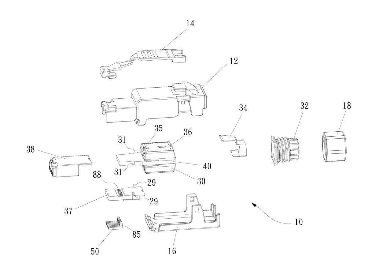
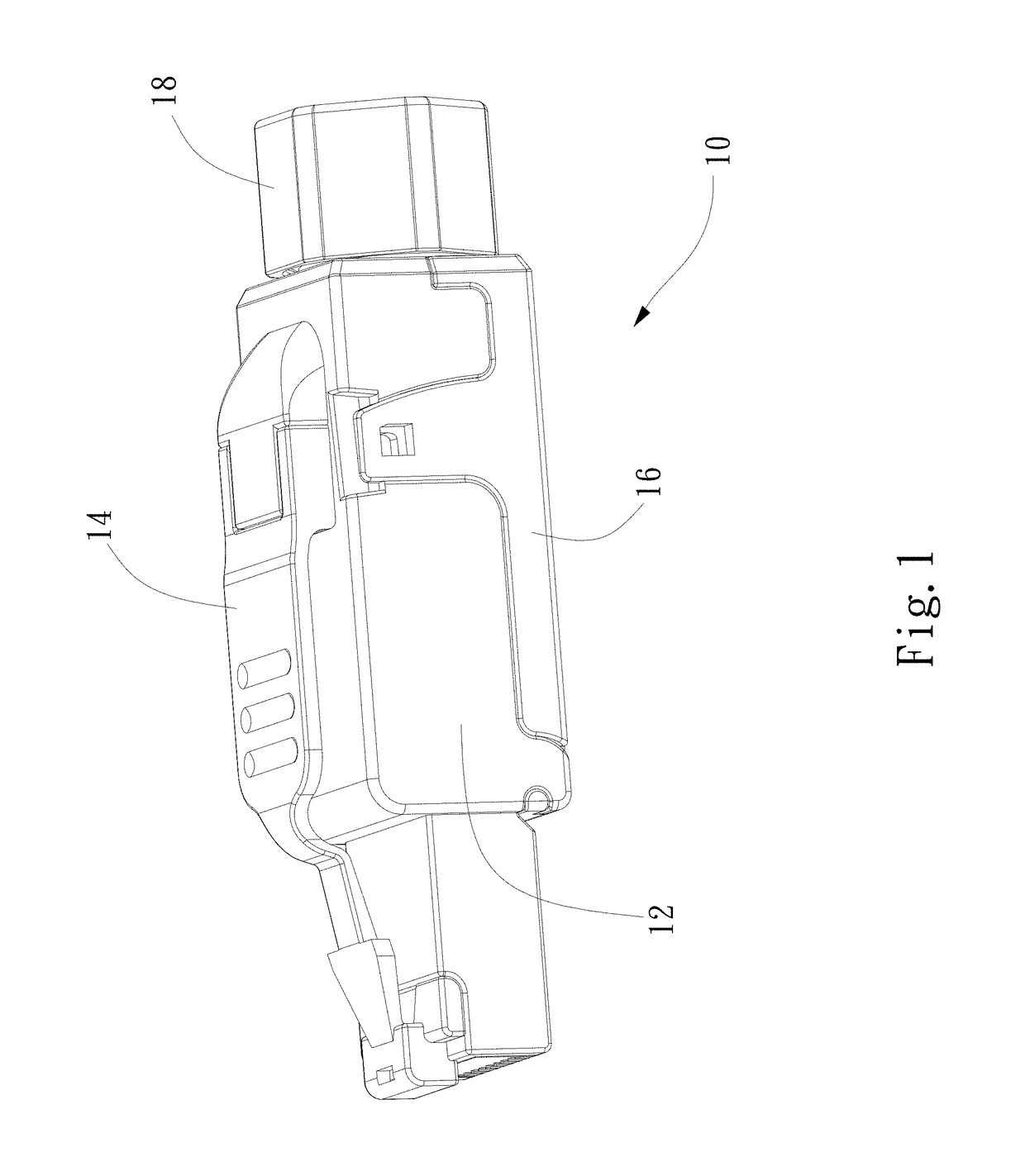
[0051]Referring to the drawings, FIG. 1 shows an RJ plug generally designated 10. The plug 10 comprises a main housing part 12 cooperating with a housing cover 16. A latch 14 is connected to an upper surface of the main housing part 12 and is used to latch the plug 10 in an electrical outlet (jack). A nut 18 provides an entry for wires of a cable (not shown) and provides a connection of the cable to the plug 10.

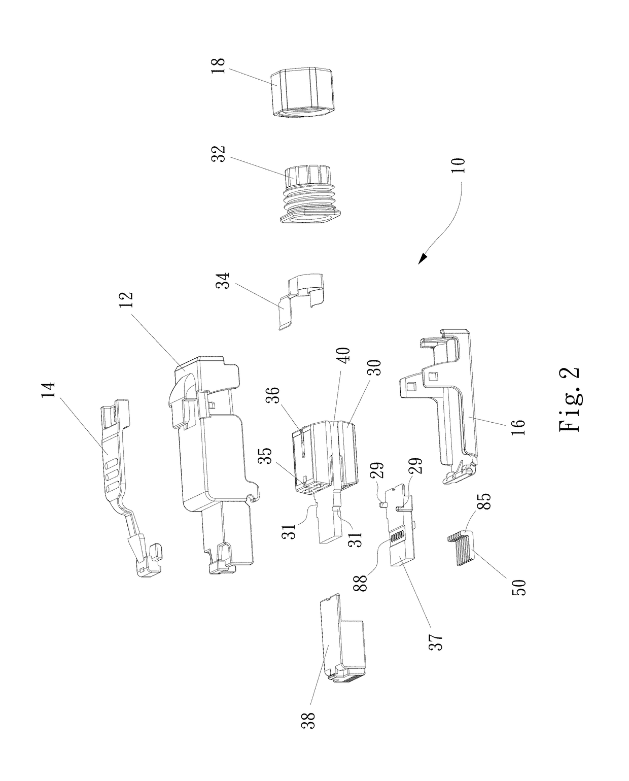
[0052]FIG. 2 shows the plug 10 in an exploded view. The main housing part 12 cooperates with the cover 16 to provide an interior space to support a printed circuit board (PCB) 40 and a wire management assembly 30. The wire management assembly 30 supports and manages connections of the wires of the cable to wire terminals. The wire terminals are insulation displacement contacts (IDCs) that are inserted (staked) into the holes of the terminal contacts 72-78 of the PCB 40 and are fixed there with a solderless press connection. The conductive wires pass through the nut 18, pass t...


PUM


Abstract

A communications plug, for high frequency applications, includes a housing, a plurality of contact conductor blades and insulation displacement contacts. A printed circuit board has a plurality of transmission paths connecting corresponding blades and insulation displacement contacts. The plug has a major coupling including coupling between the blades. The PCB further includes a compensation coupling arrangement that provides a smaller coupling as compared to the major coupling. The compensation coupling is no more than one half of the major coupling and has a different polarity from that of the major coupling. The compensation coupling is connected to a set of transmission paths at a location between the major coupling and the insulation displacement contacts.

Description

FIELD OF THE INVENTION[0001]The present invention relates to electrical connectors and more particularly relates to an RJ-45 plug for high frequency applications.BACKGROUND OF THE INVENTION[0002]Electrical connector plugs such as RJ-45 plugs have been used for network applications. These plugs include conductors wherein pairs of conductors are provided for each transmission path. Plugs such as RJ-45 plugs have eight conductors or four pairs for four different transmission lines. These may include a central pair and the split pair. With standard RJ-45 plugs, there exists huge capacitive coupling between the central pair blades and the split pair blades as well as the corresponding twisted-pair leads.[0003]For high speed or high frequency applications capacitive coupling can harm the performance of the plug-jack pair. Capacitive coupling or capacitive reactance is a component of the impedance (Z) of the plug where Z(impedance)=R(resistance)+jX(capacitive reactance+inductive reactance)...

Claims


Application Information

Patent Timeline
IPC IPC(8): H01R12/00H01R13/6469H01R13/6466H01R12/58H01R24/28H01R105/00
CPCH01R13/6466H01R13/6469H01R12/585H01R2105/00H01R2201/04H01R24/28H01R24/64H01R13/6473H05K1/02Y10S439/941
Inventor CHEN, CHOU-HSIN
Owner SURTEC INDS
Why Eureka
Try Eureka