Apparatus and method for positioning an optical element

a technology of positioning apparatus and optical element, which is applied in the field of positioning apparatus for optical element and methods for positioning optical element, can solve the problems of affecting the quality of optical elements, so as to achieve fast and accurate movement of optical elements and fast and accurate manipulation of light

Active Publication Date: 2018-11-20
NEWSON
View PDF10 Cites 1 Cited by
  • Summary
  • Abstract
  • Description
  • Claims
  • Application Information

AI Technical Summary

Benefits of technology

[0019]The present invention provides an apparatus for positioning an optical element comprising a positionable part to which the optical element can be mounted, a base part, a suspension system connecting said positionable part to said base part in a movable manner, an actuation system for actuating movement of said positionable part with respect to said base part, and optionally a control system for controlling movement of said positionable part. In an embodiment, the suspension system comprises at least one suspension element, preferably at least three or exactly three suspension elements, more preferably mechanical suspension elements, whereby preferably at least one suspension element and more preferably each suspension element, comprises a spring, such as a leaf spring, preferably a metal leaf spring. Each suspension element is attached to said base part at at least one base suspension location, thereby defining a base reference system, preferably a base reference plane. Each suspension element is also attached to said positionable part at at least one positionable suspension location, thereby defining a positionable reference system, preferably a positionable reference plane. The present suspension system allows fast and accurate movement of an optical element mounted on the positionable part, and thereby fast and accurate manipulation of a light beam reflected by or transmitted through such an optical element. An embodiment of the present invention comprising at least three or exactly three suspension elements attached to the positionable part at at least three or exactly three positionable suspension locations, is particularly preferred.
[0020]The suspension system described above allows many types of light beam manipulation, in particular three-dimensional manipulation, using only one positionable part. This greatly limits the apparatus in size and weight and allows fast and accurate deflection.
[0027]In a particularly preferred embodiment, 2 or more magnets, preferably permanent magnets, of an actuation element are disposed in an alternated pole arrangement, i.e. whereby a first magnet comprises a north pole at a proximal end, i.e. an end located near the positionable part, and a south pole at a distal end, e.g. an end located longitudinally away from the positionable part along a longitudinal direction, and whereby a second magnet, which neighbours the first magnet, comprises a south pole at the proximal end and a north pole at the distal end. Such an alternating-pole arrangement ensures that the combined magnetic field of the magnets is increased nearby the proximal ends, and thus nearby the positionable part, while the combined magnetic far-field, i.e. at long distances, is limited. This leads to a reduction of energy during operation as the high field values near the positionable part require smaller currents through the conductors of the actuating elements on the positionable part, and also leads to increased safety as the far-field is negligible and allows e.g. paramagnetic or diamagnetic material to be used relatively nearby the apparatus.

Problems solved by technology

These and other prior art devices and methods give rise to some problem, including, but not limited to, the following.
The speed of positioning and repositioning of the optical element could be severely limited in the prior art due to the weight of the positionable part of prior art devices, which can be a consequence of the actuation system of the apparatus, which may necessitate the presence of a heavy iron core on the positionable part for e.g. increasing inductive reactance; furthermore, inductive actuation may lead to considerable energy losses, especially at high positioning speeds, which could necessitate cooling systems.
Another problem with prior art devices and methods is the size of the apparatus and in particular its actuation or suspension system, which can be too large for certain applications or to be implemented into e.g. a table-top or small-scale set-up.
A further problem of prior art devices and methods is that the positionable part is usually moveable around a single axis, or, the positionable part consists of a number of sub-devices, mostly two, each of which are moveable around a single axis and which, when combined, lead to a positionable part which can be rotated around two independent axes.
However, such a setup typically requires two or more independent actuation systems, typically one actuation system for each sub-device, which increases the size and mass of the sub-devices, which in turn leads to a reduction of speed (due to e.g. increase of the mass and inertial moments of the sub-devices), a reduction of deflection range or a reduction of maximal beam width (due to e.g. connectivity or wiring difficulties, or e.g. in case of a mirroring optical element which consists of two mirrors, rotatable around perpendicular axis, where the first mirror in the optical path can be kept small, but the second mirror needs to be larger, depending on the maximal deflection angle of the first mirror).
Yet a further issue in prior art devices and methods is the lack of a possible shifting movement of the positionable part.
Another problem arising in prior art devices and methods relates to controlling the movement and / or measuring the position of the positionable part.
Such a method, however, necessitates the presence of a position measurement or sensing system, which is preferably as fast and accurate as possible in order to allow large operational speeds, while keeping costs and safety risks as low as possible.

Method used


Image

  • Apparatus and method for positioning an optical element
  • Apparatus and method for positioning an optical element
  • Apparatus and method for positioning an optical element

Examples


example

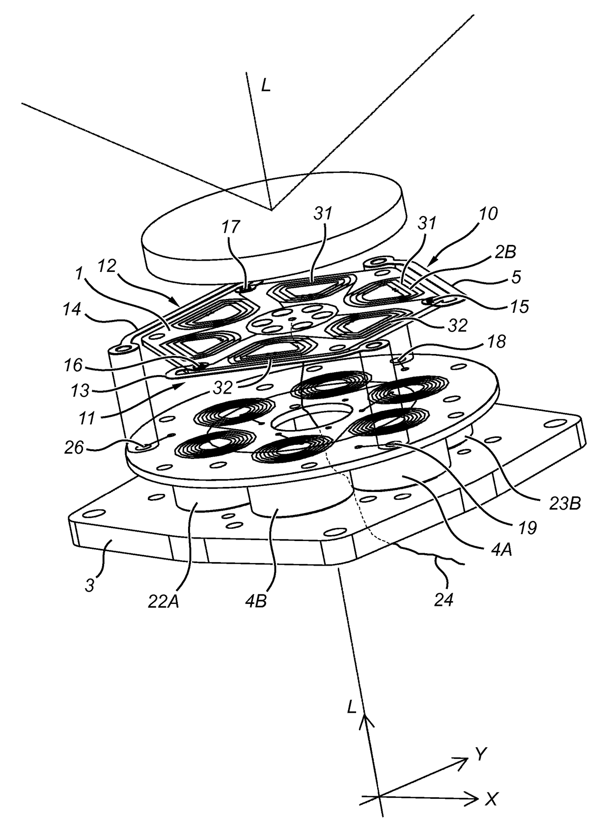
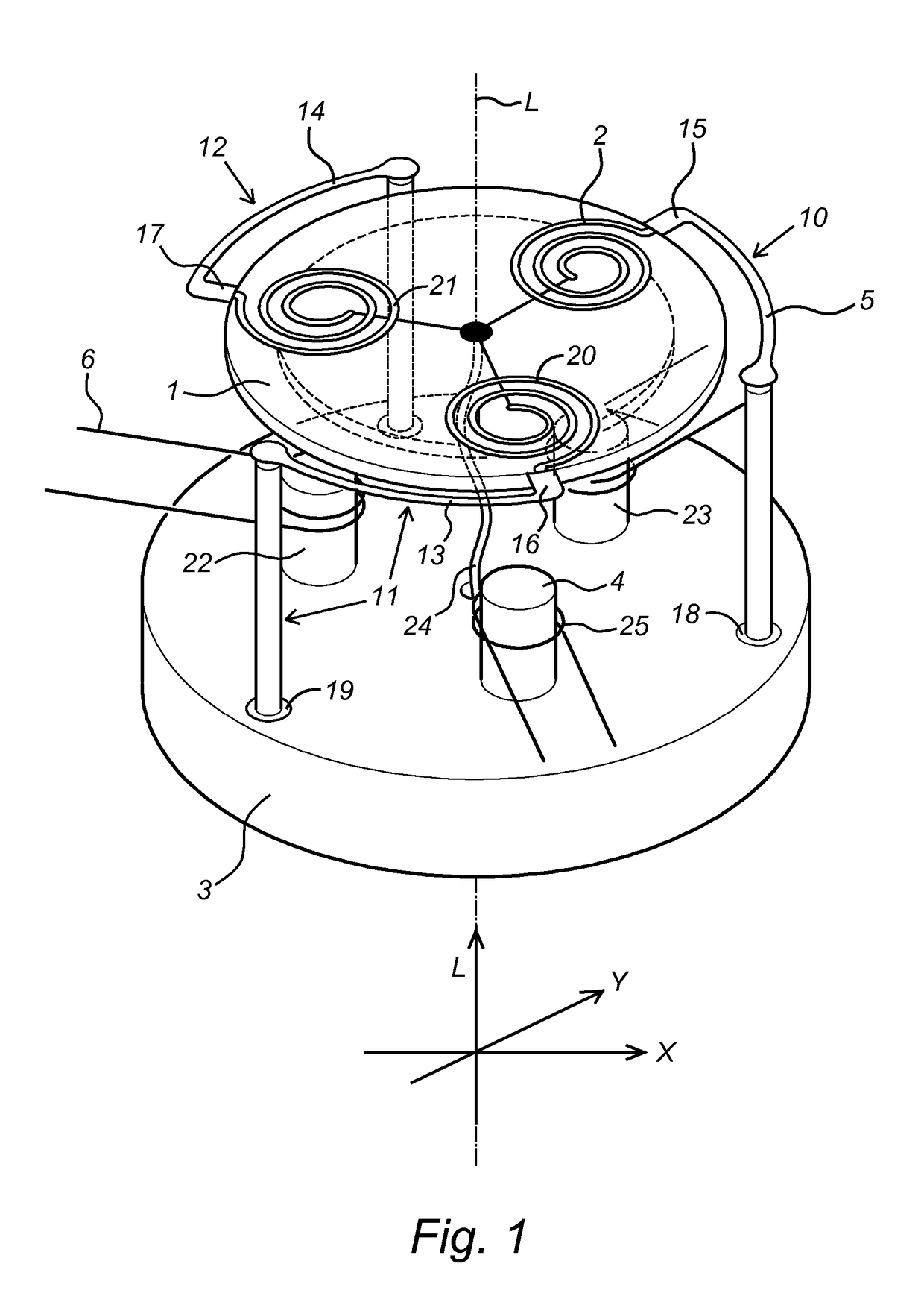
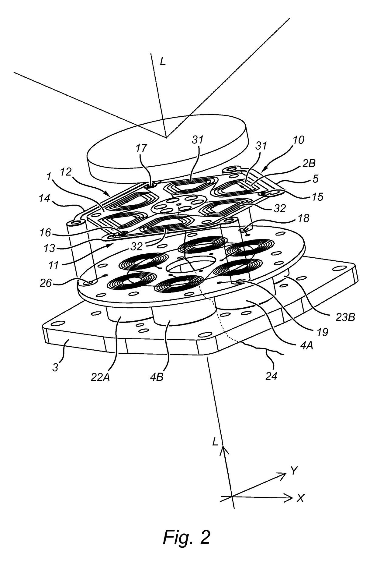
[0072]FIGS. 1-4 illustrate two embodiments of an apparatus according to the present invention. The apparatus comprises a positionable part (1), i.c. a positionable plate, to which an optical element, e.g. a mirror or lens, can be mounted. The positionable part can move with respect to a base part (3) which thus acts as a stator of the apparatus, as the positionable part is suspended by three suspension elements (10, 11, 12), each comprising a metallic leaf spring (5, 13, 14) which result in a flexible mechanical connection. The suspension elements are connected to the positionable part at position suspension points (15, 16, 17) and to the base part at base suspension points (18, 19, 26). The leaf springs are fitted to provide maximal rigidity in radial direction and maximal flexibility in axial direction (L) of the positionable part.

[0073]The actuation system of the apparatus of FIG. 1 comprises three actuation elements, each of which comprises an electrically conducting coil (2, 20...


PUM


Abstract

The current invention concerns an apparatus and a method for positioning an optical element, said apparatus comprising a positionable part to which the optical element can be mounted; a base part; a suspension system, said positionable part being mounted on said base part in a movable manner with said suspension system; an actuation system for actuating movement of said positionable part with respect to said base part; and a control system for controlling movement of said positionable part.

Description

[0001]This application claims the benefit of PCT / EP2014 / 063082 filed Jun. 20, 2014, International Publication No. WO 2015 / 192914, and the amended sheets from the IPRP, which are hereby incorporated by reference in their entirety as if fully set forth herein.TECHNICAL FIELD[0002]The invention pertains to the technical field of positioning apparatus for an optical element and methods for positioning an optical element, more in particular an apparatus capable of rotating and / or shifting an optical element with respect to an optical beam axis.BACKGROUND[0003]Apparatus for positioning optical elements within an optical beam axis are necessary in many applications, in particular in applications concerned with laser manipulation processes such as laser scanning, laser engraving, laser marking, laser ablation or laser etching, but also other application which necessitate deflection of a light beam, whether incoherent, coherent or partially coherent, according in a controllable manner.[0004]...

Claims


Application Information

Patent Timeline
Patent Type & Authority Patents(United States)
IPC IPC(8): G02B26/08G01D5/20G02B7/182
CPCG02B26/08G02B7/1827G01D5/20G02B7/1828G02B26/0816G02B26/101
Inventor VAN BIESEN, MARC
Owner NEWSON
Why Eureka
Try Eureka