Relief cylinder structure of a multinip calender

a cylinder and cylinder technology, applied in the field of cylinder structure, can solve the problems of production breakage, production defect, easy damage to the polymer coating of the calender roll, etc., and achieve the effect of easy implementation

Inactive Publication Date: 2008-02-05
VALMET TECH INC
View PDF15 Cites 0 Cited by
  • Summary
  • Abstract
  • Description
  • Claims
  • Application Information

AI Technical Summary

Benefits of technology

[0012]The basic idea of the invention is to implement a relief cylinder structure in such a manner that its quick-opening cylinder is placed inside the arm of the relief cylinder. By means of the structure according to the invention it is in a fault situation possible to rapidly change the shape and size of the arm in relation to the main cylinder of the relief cylinder, thus producing a fast movement of the cylinder.
[0015]The compression of the structure substantially corresponds to the change in the volume of the quick-opening cylinder, i.e. by means of a small volume a small movement is attained and by means of a large volume a broad movement is attained. Because the quick-opening movement is proportional to the volume of the quick-opening cylinder, it is possible to accurately determine the breadth of the quick-opening movement, and thus to attain a fast and accurate opening movement in case of a fault situation.
[0017]Furthermore, the structure of a relief cylinder enabling the quick-opening according to the invention requires a smaller number of parts, and at the same time it can be implemented more easily than solutions of prior art.

Problems solved by technology

The polymer coating of the calender rolls is an easily damaging component of the machine.
If the use of the roll in production continues in spite of the incipient damage, the damage grows, causes defects in the production quality (marking of paper), production breaks (unplanned stoppage resulting from the changing of the damaged roll), and in the worst case risks in occupational safety (sudden loosening of the damaged coating, pieces of coating flying rapidly in the environment).

Method used


Image

  • Relief cylinder structure of a multinip calender
  • Relief cylinder structure of a multinip calender
  • Relief cylinder structure of a multinip calender

Examples


Embodiment Construction

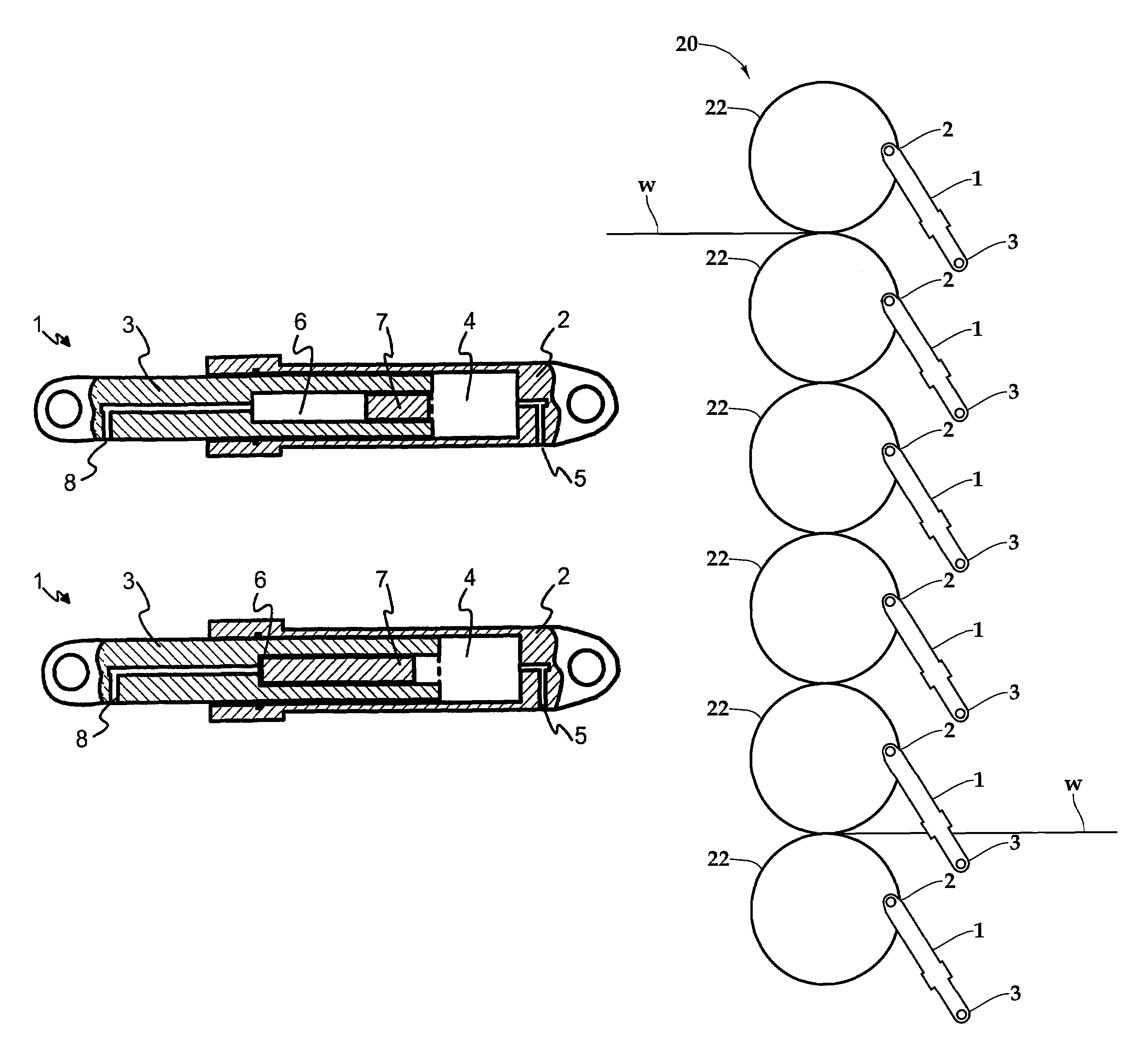
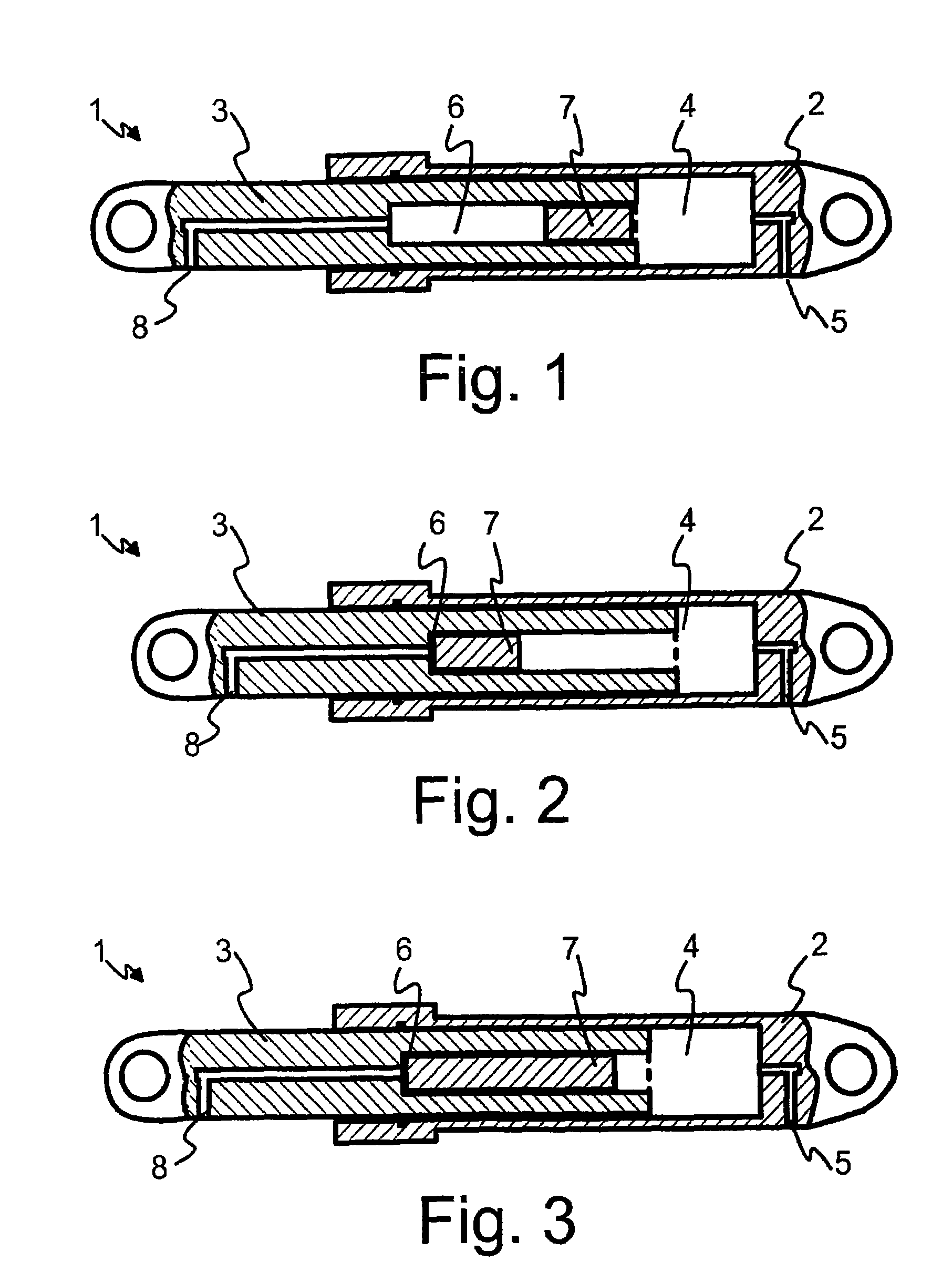
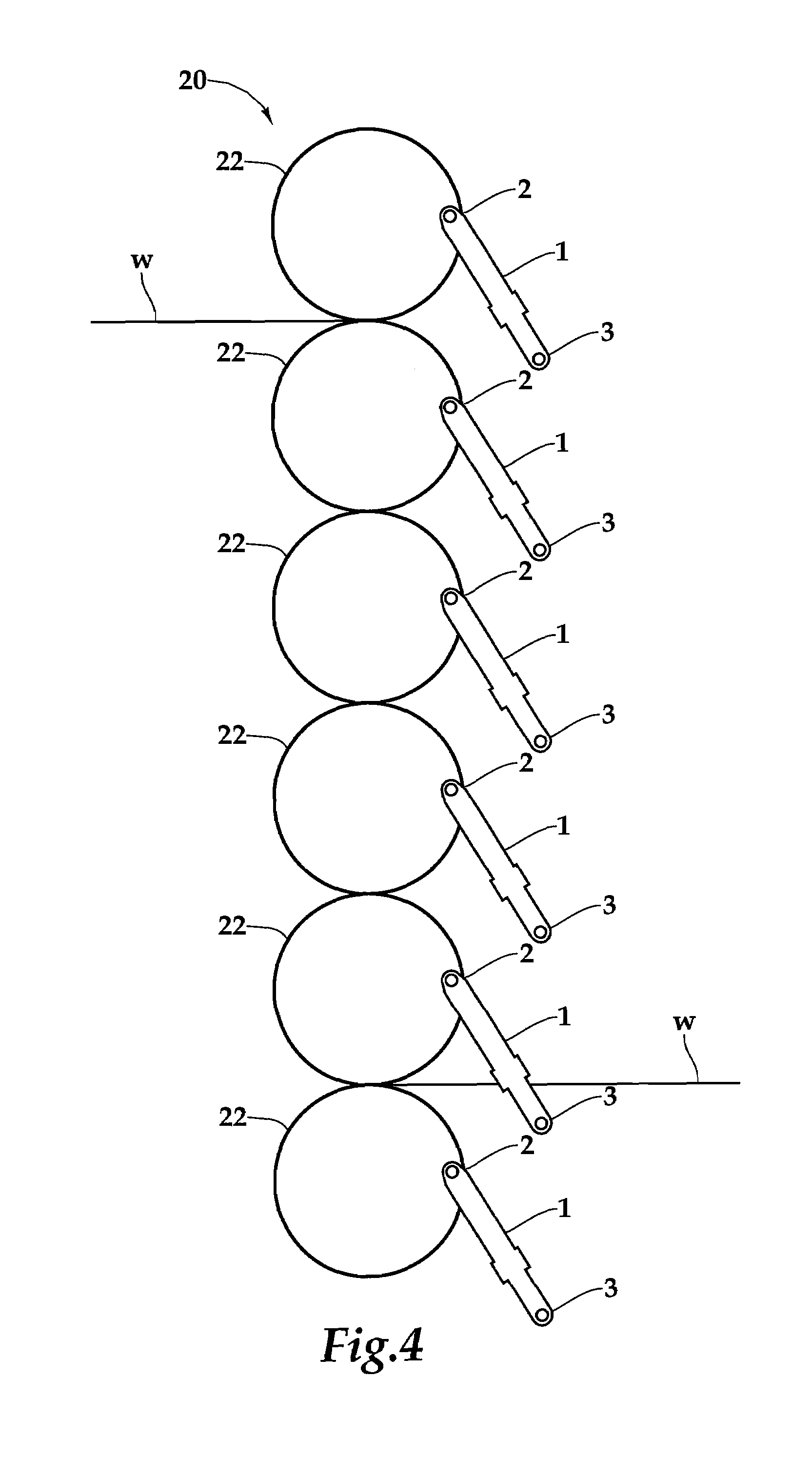
[0023]FIG. 1 shows an embodiment of the relief cylinder structure 1 according to the invention that comprises a cylinder frame 2 and a piston-like arm 3 arranged to move therein. Inside the frame 2, in the area defined by the arm, an area is formed, for which the term main cylinder 4 will be used hereinbelow. To the main cylinder 4 is connected a hydraulic coupling 5 placed in the frame 2, the term main coupling 5 being used hereinbelow for said coupling. The other end of the main coupling 5 is advantageously placed close to the end of the frame 2, from which it can be easily connected to the hydraulic system. The gap between the frame 2 and the arm 3 is advantageously sealed in a known manner.

[0024]According to the invention, a quick-opening cylinder 6 is arranged inside the arm 3, and an auxiliary piston 7 is arranged to move therein. To the quick-opening cylinder 6 is connected a hydraulic coupling 8, the term auxiliary coupling 8 being used for said coupling hereinbelow. The aux...


PUM


Abstract

A relief cylinder structure for guiding a roll in a multinip calender has a frame and an arm that is arranged to move linearly in relation to the frame. A quick-opening cylinder is placed inside the arm. In a fault situation, the relief cylinder causes the cylinder rolls to move rapidly further away from each other. An auxiliary coupling (8) opens in a fault situation, wherein the pressure produced in the quick-opening cylinder (6) is discharged to a hydraulic system in a substantially non-pressurized state. The pressure of the quick-opening cylinder (6) is thus reduced below the pressure of the main cylinder (4), wherein the auxiliary piston (7) moves towards the end of the arm (3). Because the volume of the main cylinder (4) grows in accordance with the cylindrical space formed inside the arm (3), the volume restricted by the frame (2) of the relief cylinder (1) is reduced.

Description

CROSS REFERENCES TO RELATED APPLICATIONS[0001]This application is a U.S. national stage application of PCT App. No. PCT / FI03 / 00452, filed Jun. 9, 2003, the disclosure of which is incorporated by reference herein, and claims priority on Finnish Application U20020278, Filed Jun. 10, 2002.STATEMENT AS TO RIGHTS TO INVENTIONS MADE UNDER FEDERALLY SPONSORED RESEARCH AND DEVELOPMENT[0002]Not applicable.BACKGROUND OF THE INVENTION[0003]The invention relates to a relief cylinder structure for guiding the roll of a multinip calender. The invention also relates to an arm used in a relief cylinder structure.[0004]A paper web is calendered by passing it through at least one calender nip. It is a known process to use a so-called soft calender in which the web is passed through a nip formed by a hard-faced metal roll and a soft-faced roll. The soft-faced roll is typically formed by coating the roll frame with a suitable polymer material.[0005]The calender may also contain several nips successivel...

Claims


Application Information

Patent Timeline
Patent Type & Authority Patents(United States)
IPC IPC(8): B30B3/04D21G1/00
CPCD21G1/002
Inventor HAAG, JORMALAAKSONEN, KEIJO
Owner VALMET TECH INC
Why Eureka
Try Eureka