Motor control apparatus

a technology of motor control and motor shaft, which is applied in the direction of ac motor acceleration/deceleration control, electronic commutator, stopping arrangement, etc., can solve the problem of limiting the applicability according to the product, and achieve the effect of easy learning the initial position of the rotor

Active Publication Date: 2018-11-06
DENSO CORP
View PDF10 Cites 0 Cited by
  • Summary
  • Abstract
  • Description
  • Claims
  • Application Information

AI Technical Summary

Benefits of technology

[0008]The two-stage drive method disclosed in Patent Literature 1 requires the time for initial drive. Further, the method of devising the product assembly by using the spring or the like can limit the applicability depending on the product.
[0009]It is an object of the present disclosure to provide a motor control apparatus that easily learns an initial position of a rotor at the start of activation without two-stage drive or devised product assembly.
[0011]According to the present disclosure, it may be possible to learn that the initial position of the rotor is the two-phase facing position or the one-phase facing position based on values of the A-phase signal and the B-phase signal at the time of energizing two phases out of three phases. Hence it may be possible to easily learn the initial position of the rotor at the start of activation without two-stage drive or devised product assembly.
[0012]Further, in the present disclosure, since two phases out of the three phases are energized in learning the initial position, it may be possible to learn the initial position even when one phase is disconnected.

Problems solved by technology

Further, the method of devising the product assembly by using the spring or the like can limit the applicability depending on the product.

Method used


Image

  • Motor control apparatus
  • Motor control apparatus
  • Motor control apparatus

Examples


embodiment

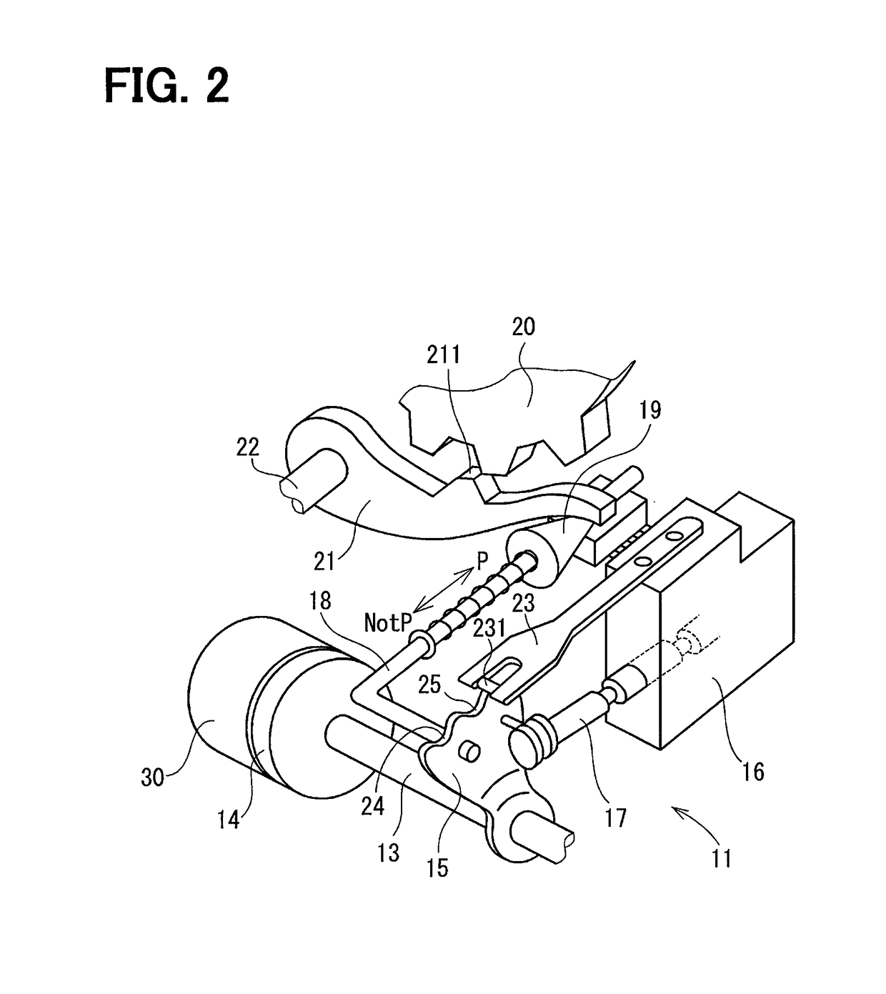
[0027]With reference to FIGS. 1 to 6, descriptions are given of the motor control apparatus according to one embodiment of the present disclosure, and a range switching apparatus for an automatic transmission, to which the motor control apparatus is applied.

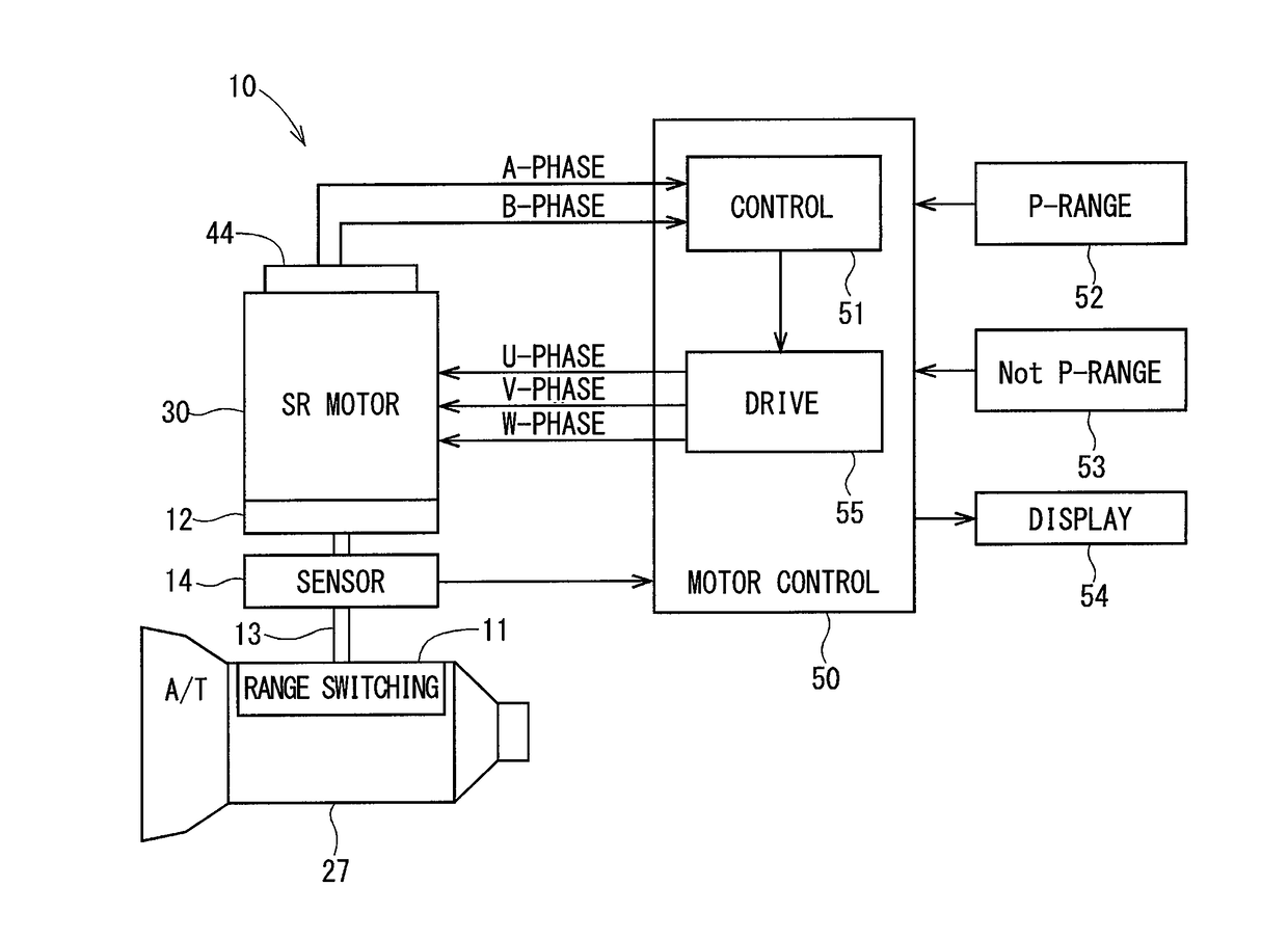
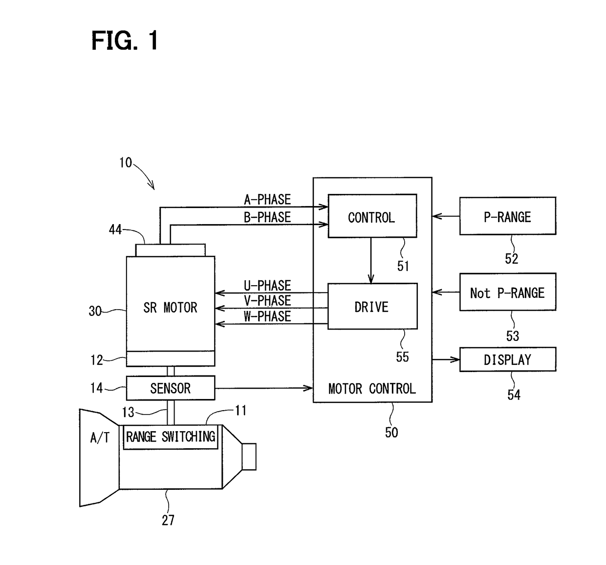
[0028]An overall configuration of a range switching apparatus 10 is described with reference to FIGS. 1 and 2. The range switching apparatus 10 corresponds to one example of the actuator.

[0029]As shown in FIG. 1, the range switching apparatus 10 includes a motor 30 that is a drive source for a range switching mechanism 11, and an encoder 44 that detects a rotor rotational position of the motor 30. The motor 30 is configured of, for example, a switched reluctance motor (hereinafter referred to as SR motor) and has a deceleration mechanism 12 built therein.

[0030]An output shaft sensor 14 is provided to an output shaft 13 connected to the deceleration mechanism 12 of the SR motor 30. The output shaft sensor 14 is configured of, for ...


PUM


Abstract

A motor control apparatus which is applied to an actuator provided with a motor and an encoder, and drives the motor is provided. The motor control apparatus comprises: a controller that learns an initial position of a rotor, and also decides an energized phase; and a drive circuit that performs switching operation to energize an energized phase. The controller learns that, in learning the initial position, the initial position of the rotor is a two-phase facing position in which two adjacent salient poles of the rotor face salient poles of two energized phases of a stator, and the initial position of the rotor is a one-phase facing position in which one salient pole of the rotor faces a salient pole of one non-energized phase of the stator.

Description

CROSS-REFERENCE TO RELATED APPLICATION[0001]This application is the U.S. national phase of International Application No. PCT / JP2016 / 000846 filed Feb. 18, 2016, which designated the U.S. and claims priority to Japanese Patent Application No. 2015-35186 filed on Feb. 25, 2015, the entire contents of each of which are hereby disclosure of which is incorporated herein by reference.TECHNICAL FIELD[0002]The present disclosure relates to a motor control apparatus that sequentially switches an energized phase of a motor on the basis of output signals of an encoder to rotationally drive a rotor.BACKGROUND ART[0003]As for a control device for driving a motor such as a switched reluctance motor, there is known a motor control apparatus that counts pulse signals outputted by an encoder in synchronization with rotation of a rotor, detects a rotational position of the rotor on the basis of the count values, and sequentially switches an energized phase, to rotationally drive the rotor.[0004]This k...

Claims


Application Information

Patent Timeline
Patent Type & Authority Patents(United States)
IPC IPC(8): H02K3/00H02P6/24H02P23/20H02P6/16H02P25/08H02P1/16H02P25/092
CPCH02P6/16H02P1/163H02P25/08H02P25/0925
Inventor SAKAGUCHI, KOJI
Owner DENSO CORP
Why Eureka
Try Eureka