
Air-conditioning-apparatus outdoor unit and method of manufacturing air-conditioning-apparatus outdoor unit

a technology of air-conditioning equipment and outdoor units, which is applied in indirect heat exchangers, lighting and heating equipment, heating types, etc., can solve problems such as freezing or corrosion, and achieve the effects of reducing the flow rate of air passing through the heat exchanger, reducing the cost, and reducing the heat exchanger

Active Publication Date: 2018-10-30
MITSUBISHI ELECTRIC CORP
View PDF20 Cites 0 Cited by
  • Summary
  • Abstract
  • Description
  • Claims
  • Application Information

AI Technical Summary

Benefits of technology

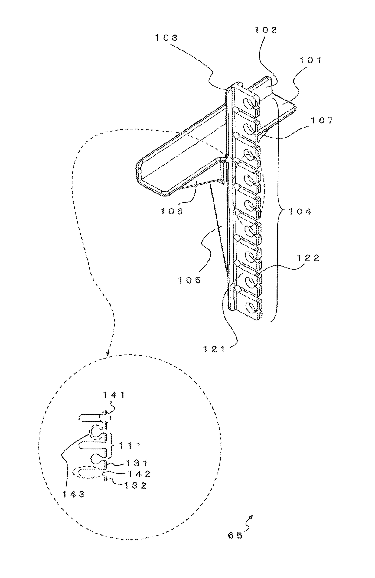
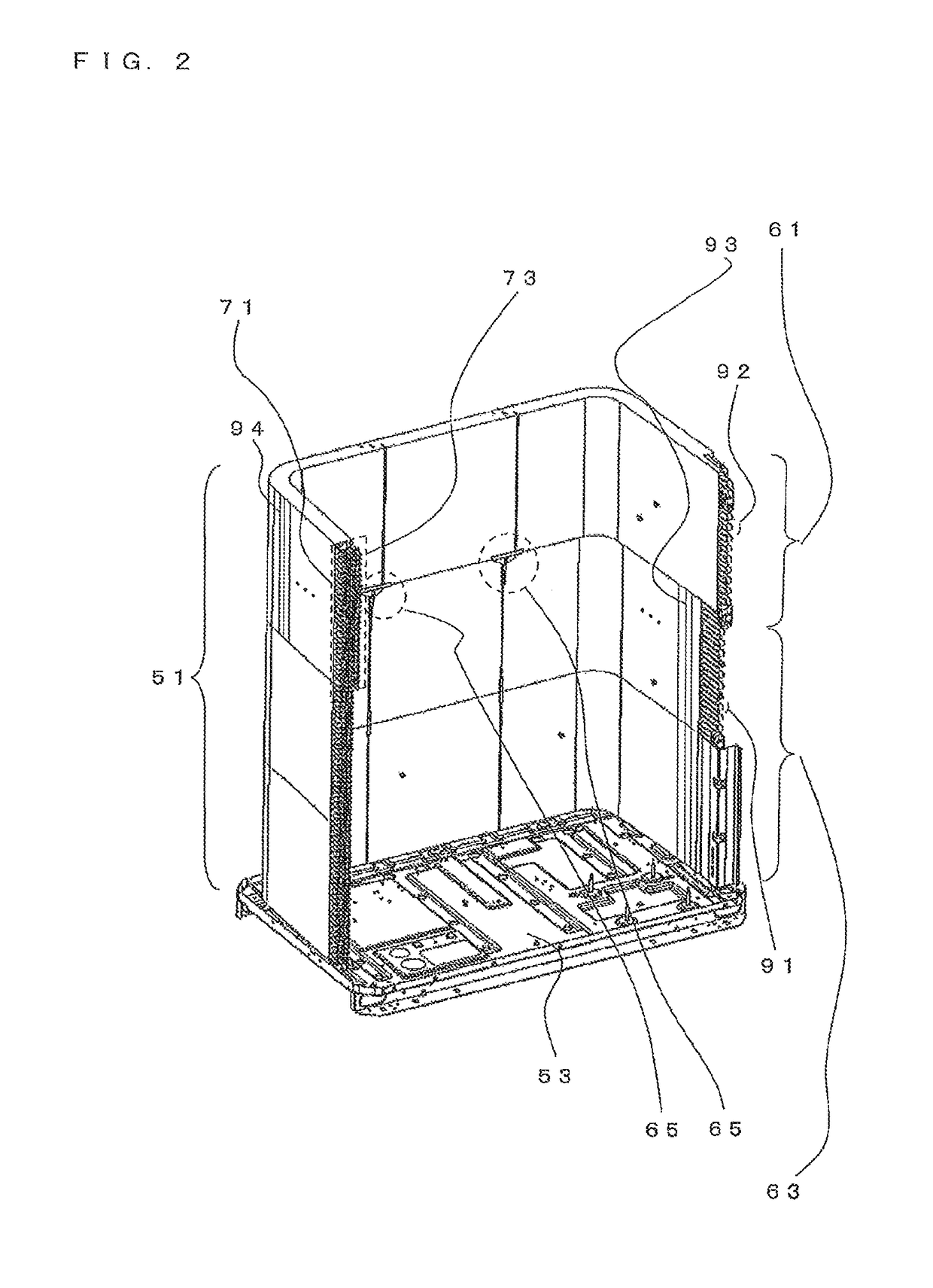
[0024]According to the present invention, by supporting the bottom of the lowest heat-transfer tube of the heat exchanger provided on the upper side with a reinforcing member that forms an air passage, the heat exchanger provided on the upper side is supported, without the strength of the bottom plate that supports the heat exchanger being decreased and without the flow rate of air passing through the heat exchanger being decreased. Hence, the present invention has an advantage in that it is possible to reliably avoid, at low cost, falling off of the heat exchanger provided on the upper side, even when vibration due to operation or vibration due to transportation occurs.

Problems solved by technology

Because the bottom plate collects dew condensation water produced by the heat exchanger, it causes freezing or corrosion.

Method used


Image

  • Air-conditioning-apparatus outdoor unit and method of manufacturing air-conditioning-apparatus outdoor unit
  • Air-conditioning-apparatus outdoor unit and method of manufacturing air-conditioning-apparatus outdoor unit
  • Air-conditioning-apparatus outdoor unit and method of manufacturing air-conditioning-apparatus outdoor unit

Examples


embodiment 1

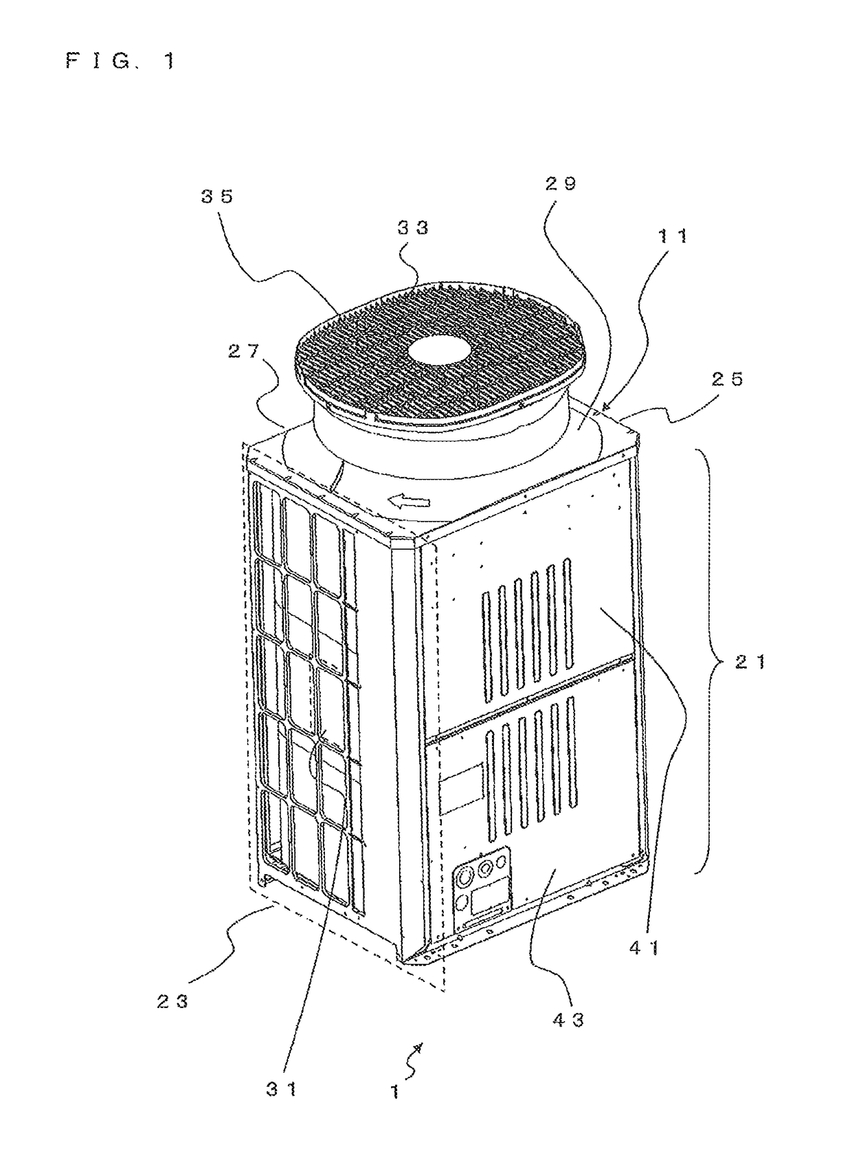
[0032]FIG. 1 is a perspective view of an outdoor unit for an air-conditioning-apparatus 1 according to Embodiment 1 of the present invention. As shown in FIG. 1, the outer surface side of the outdoor unit 1 is formed of a housing 11. The housing 11 is formed of a front panel 21, a first side panel 23, a second side panel 25, a rear panel 27, a top panel 29, etc.

[0033]The front panel 21 is formed of an upper front panel 41 and a lower front panel 43. The upper front panel 41 and the lower front panel 43 are opened and closed when an operator performs maintenance or the like on the inside of the housing 11. The first side panel 23, the second side panel 25, and the rear panel 27 each has air inlets 31. The top panel 29 has an air outlet 33. A fan 35 is provided inside the housing 11. When the fan 35 is driven, a negative pressure is generated inside the housing 11, drawing the air around the housing 11 from the respective air inlets 31 and blowing the drawn air from the air outlet 33....


PUM

PropertyMeasurementUnit
angleaaaaaaaaaa
thicknessaaaaaaaaaa
pressureaaaaaaaaaa

Abstract

An outdoor unit includes: a lower heat exchanger having a first heat-transfer tube; an upper heat exchanger provided above the lower heat exchanger, including a first-row heat-exchanger core and a second-row heat-exchanger core, and a second heat-transfer tube; and a reinforcing member supporting the upper heat exchanger, wherein the reinforcing member includes a first supporting tab supporting the bottom of the second-row heat-exchanger core; a second supporting tab supporting the lower side surface of the second-row heat-exchanger core and formed integrally with the first supporting tab; a third supporting tab providing a gap between the first-row heat-exchanger core and the second-row heat-exchanger core and formed integrally with the first supporting tab; an engaging tab holding the first heat-transfer tubes and formed integrally with the third supporting tab; and an engaging tab holding the second heat-transfer tubes and formed integrally with the third supporting tab.

Description

CROSS REFERENCE TO RELATED APPLICATION[0001]This application is a U.S. national stage application of International Application No. PCT / JP2013 / 066477 filed on Jun. 14, 2013, the disclosure of which is incorporated herein by reference.TECHNICAL FIELD[0002]The present invention relates to an outdoor unit for an air-conditioning-apparatus and a method of manufacturing the outdoor unit for an air-conditioning-apparatus.BACKGROUND ART[0003]Air-conditioning-apparatus outdoor units that are installed in buildings, commercial facilities, or the like these days have a heat exchanger that is disposed along a rear surface and side surfaces and a fan that is disposed on a top surface. By driving the fan, a negative pressure is formed inside, a flow of air is produced around the heat exchanger, and then heat exchange using the heat exchanger is performed.[0004]The heat exchanger is formed such that heat-transfer tubes perpendicularly penetrate through fins. The heat-transfer tubes are, for exampl...

Claims


Application Information

Patent Timeline
Patent Type & Authority Patents(United States)
IPC IPC(8): F28F9/00F28D1/047F28D1/04F28F9/013F28D1/00F28F9/04F24F1/56F24F1/16B23P15/26F24F13/30F24F13/22
CPCF24F1/56B23P15/26F24F1/16F24F13/30F28D1/0477F28F9/0131F28F9/0132F28D1/0426F24F2013/221
Inventor MORIKAWA, YUUDAIINAGAKI, TOMOKI
Owner MITSUBISHI ELECTRIC CORP
Learn More