
Brushless alternator field coil bobbin apparatus

a brushless alternator and field coil technology, which is applied in the direction of windings, magnetic circuit rotating parts, magnetic circuit shapes/forms/construction, etc., can solve the problems of increasing the amount of field coil material, preventing material reduction, and large disposal rate of material, so as to reduce the amount of material in the field coil and reduce the cost

Active Publication Date: 2005-03-03
MITSUBISHI ELECTRIC CORP
View PDF3 Cites 1 Cited by
  • Summary
  • Abstract
  • Description
  • Claims
  • Application Information

AI Technical Summary

Benefits of technology

[0010] An object of the present invention is to provide a brushless alternator field coil bobbin apparatus ensuring vibration resistance and enabling reductions in cost by reducing the amount of field coil material by adopting a joining construction between a yoke portion and a plate that reduces an inside diameter of a bobbin while ensuring supporting strength for the plate.
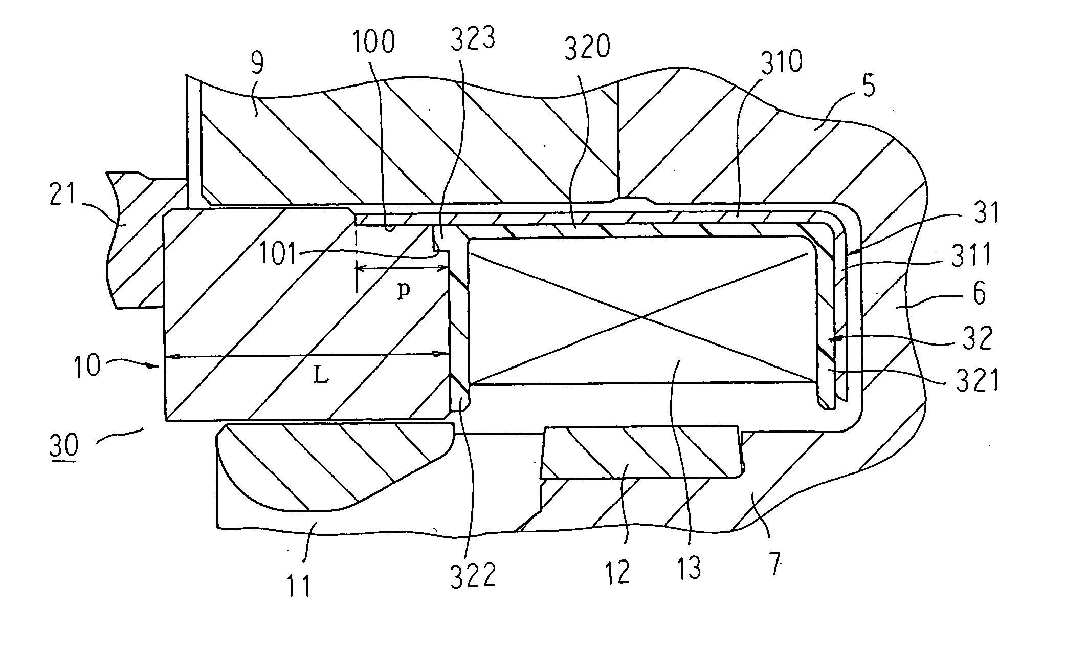
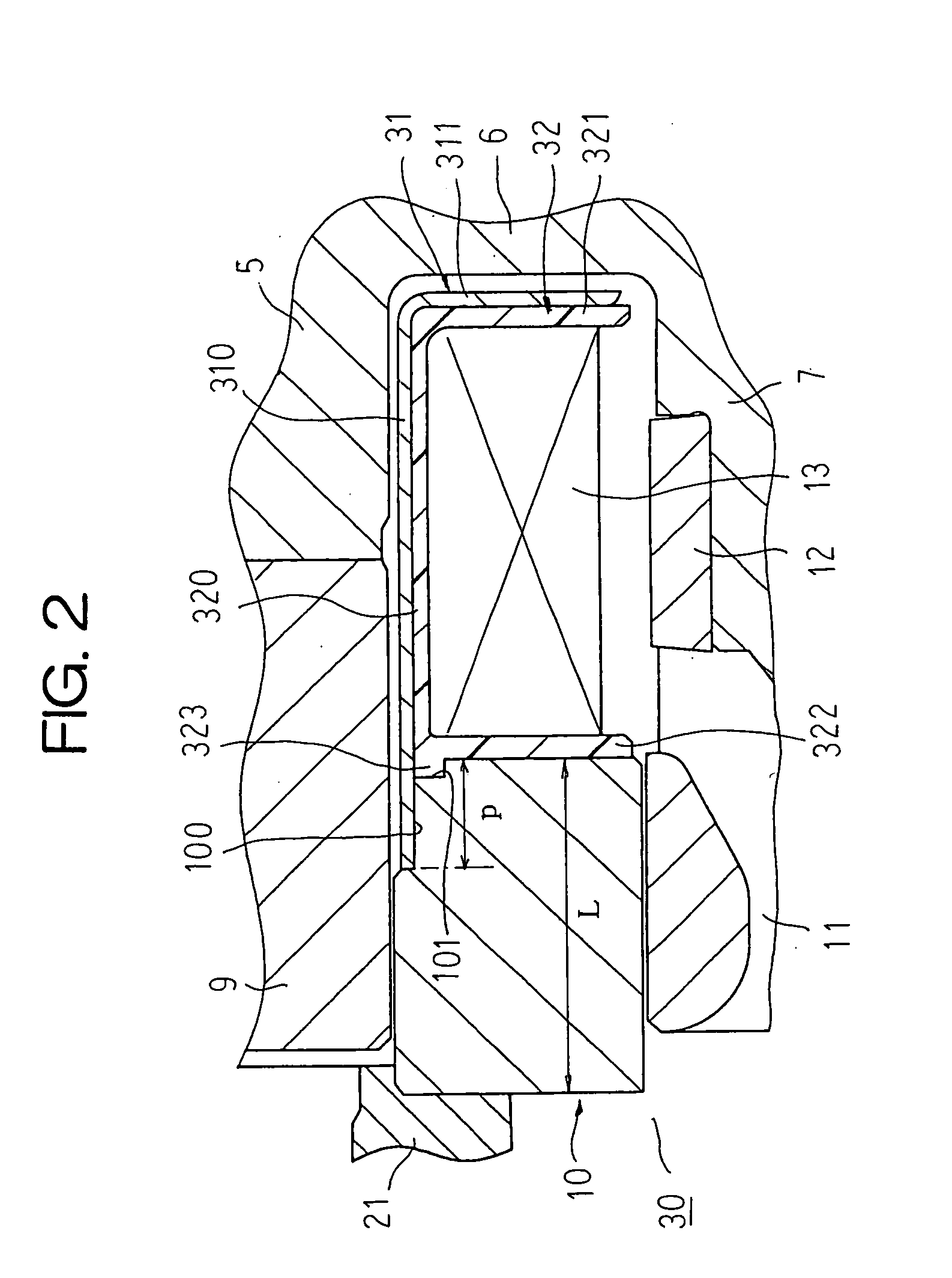
[0012] According to the present invention, a plate is supported by a yoke portion in a state of surface contact, ensuring supporting strength for the plate. In addition, because the plate is welded directly onto the yoke portion axially outside a bobbin, an inside diameter of the bobbin is reduced, enabling material in the field coil to be reduced, thereby enabling reductions in cost.

Problems solved by technology

As a result, because the winding diameter of the field coil is larger, increasing the length of the conducting wire, one disadvantage has been that the amount of field coil material is increased, preventing reductions in cost.
Furthermore, because a yoke portion having a thin portion is prepared from a round bar by turning, other disadvantages have been that the disposal rate of material is large and manufacturing time is lengthy, thereby preventing reductions in cost.
Because the cylindrical portion of the plate and the thin portion of the yoke portions are welded through welding apertures disposed through the cylindrical portion of the bobbin, another disadvantage has been that if there are changes in position or increases in the number of welds accompanying changes in the welding specification, it is necessary to prepare a bobbin in which the position and number of welding apertures are modified, reducing the degree of design freedom and also preventing reductions in cost.
However, because the plates are then supported by the yoke portions using a cantilever construction, a first end of the plates that is farthest away from the portion fixed to the yoke portion becomes a free end, giving rise to new problems such as the plate vibrating significantly when mounted to an alternator.

Method used


Image

  • Brushless alternator field coil bobbin apparatus
  • Brushless alternator field coil bobbin apparatus
  • Brushless alternator field coil bobbin apparatus

Examples


embodiment 1

[0018] Embodiment 1

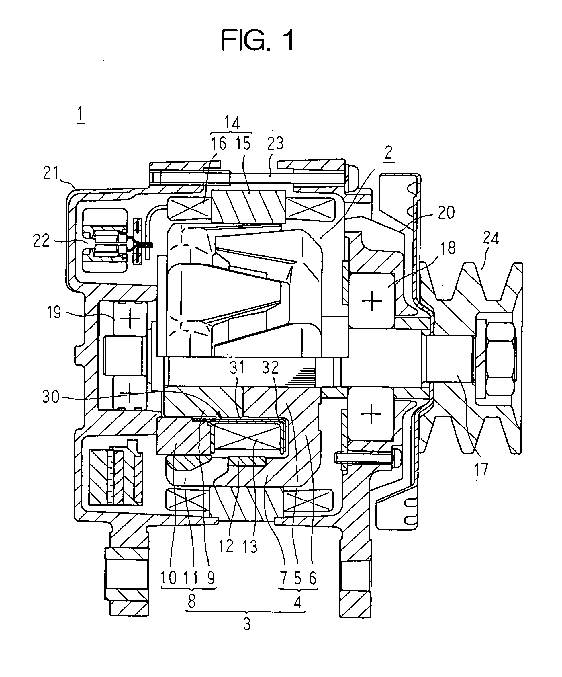
[0019]FIG. 1 is a longitudinal section showing a brushless alternator according to Embodiment 1 of the present invention, FIG. 2 is a partial enlarged cross section showing a vicinity of a bobbin apparatus of a field coil in the brushless alternator shown in FIG. 1, and FIG. 3 is a perspective showing a plate used in the bobbin apparatus of the field coil in the brushless alternator according to Embodiment 1 of the present invention.

[0020] In FIG. 1, a brushless alternator 1 is constituted by: a magnetic pole core 3 of a rotor 2 functioning as a field; a field coil 13 secured in a position surrounded by magnetic poles of the magnetic pole core 3 and together with the magnetic pole core 3 constituting the rotor 2; a stator 14 functioning as an armature; first and second bearings 18 and 19 for rotatably supporting a shaft 17 constituting a rotating shaft of the rotor 2; first and second brackets 20 and 21; and a rectifier 22 electrically connected to the stator 14 ...

embodiment 2

[0046] Embodiment 2

[0047]FIG. 4 is a perspective showing a plate used in a bobbin apparatus of a field coil in a brushless alternator according to Embodiment 2 of the present invention.

[0048] In FIG. 4, a plate 40 is prepared by press-forming a soft steel plate, and is provided with: a cylindrical portion 400 having a hollow cylindrical shape; a disk-shaped flange portion 401 disposed so as to extend radially outward from a first end of the cylindrical portion 400; and four tongue segments 402 disposed so as to extend axially outward from a second end of the cylindrical portion 400. The four tongue segments 402 are formed on the cylindrical portion 400 at a uniform angular pitch in a circumferential direction, each being formed to an axial length p and a circumferential width 1.

[0049] Furthermore, although not shown, four stepped portions having a circumferential width 1 and an axial length p are formed at a uniform angular pitch in a circumferential direction on an inner circumfe...


PUM


Abstract

An annular stepped portion is formed at a first end of an inner circumferential surface of a thick ring-shaped second yoke portion, a second axial end portion of a cylindrical portion of a plate is fitted inside so as to overlap with the stepped portion in a radial direction, and the cylindrical portion of the plate is integrated with the second yoke portion by welding in the radially-overlapping region.

Description

BACKGROUND OF THE INVENTION [0001] 1. Field of the Invention [0002] The present invention relates to a bobbin apparatus for holding a field coil of a brushless alternator and particularly to a joining construction between a yoke portion and a plate constituting the bobbin apparatus. [0003] 2. Description of the Related Art [0004] Conventional bobbin apparatuses for holding a field coil of a brushless alternator are provided with: a yoke portion composed of a thick cylindrical thick portion and a thin cylindrical thin portion disposed so as to protrude axially from a minimum radius portion of this thick portion; a plate composed of a cylindrical portion and a disk-shaped flange portion disposed so as to extend radially outward from one end of this cylindrical portion; and a bobbin composed of a cylindrical portion and a pair of disk-shaped flange portions disposed so as to extend radially outward from two ends of this cylindrical portion. The cylindrical portion of the bobbin is moun...

Claims


Application Information

Patent Timeline
IPC IPC(8): H02K3/46H02K3/52H02K5/24H02K1/22H02K19/22
CPCH02K3/528
Inventor KURODA, MOTOKAZUHIGASHINO, KYOKO
Owner MITSUBISHI ELECTRIC CORP
Learn More