
Power over ethernet power distribution system using dominant and non-dominant sensors

a technology of power distribution system and sensor, applied in the direction of program control, mechanical power/torque control, ratio control, etc., can solve the problem of relatively high power consumption within the poe power distribution system, and achieve the effect of reducing power consumption

Active Publication Date: 2018-10-09
SIGNIFY HLDG BV
View PDF13 Cites 0 Cited by
  • Summary
  • Abstract
  • Description
  • Claims
  • Application Information

AI Technical Summary

Benefits of technology

The present invention provides a power distribution system, method, and computer program that reduces power consumption. The system includes a power providing unit that assigns sensors to different classes (dominant and non-dominant) based on their importance in detecting events. Only the dominant sensors are assigned to the low power mode, reducing power consumption by about 80%. After an event is sensed, power is quickly provided to both the dominant and non-dominant sensors. This reduces power consumption and improves efficiency in sensor-based systems.

Problems solved by technology

The PoE power distribution system is often operable in a normal operation mode and in a standby mode, wherein even in the standby mode the power consumption within the PoE power distribution system can be relatively high.

Method used


Image

  • Power over ethernet power distribution system using dominant and non-dominant sensors
  • Power over ethernet power distribution system using dominant and non-dominant sensors
  • Power over ethernet power distribution system using dominant and non-dominant sensors

Examples


Embodiment Construction

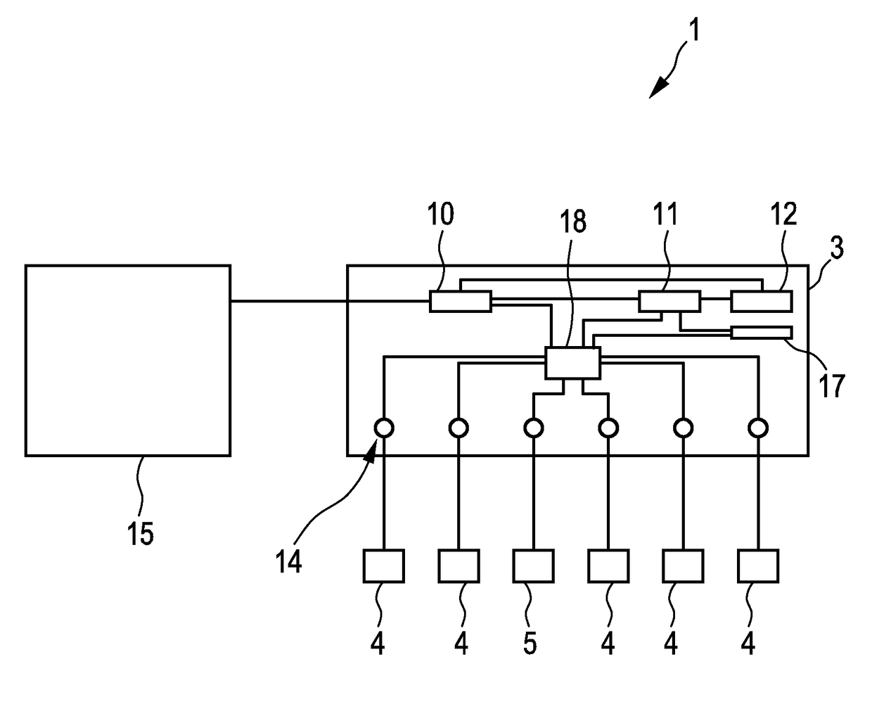
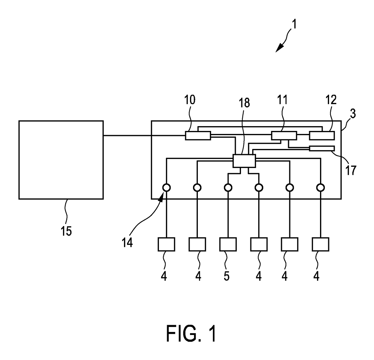
[0042]FIG. 1 shows schematically and exemplarily an embodiment of a power distribution system. The power distribution system 1 comprises a power providing unit 3 being, in this embodiment, a PoE switch having several ports 14. The PoE switch 3 comprises a PSU 10, which is adapted to receive power from an external power source 15 like a mains power source of a building and to transform the received power to DC power to be supplied to PDs 4 and other electrical consumers 5. The PoE switch 3 further comprises a power distribution unit 18 for distributing the power provided by the PSU 10 among the ports 14, a communication unit 17 for providing Ethernet communication, an assignment providing unit 12 which will be described further below and a controller 11 for controlling the different components of the PoE switch 3. The PoE switch 3 can comprise further components, which are not shown in FIG. 1 for clarity reasons.

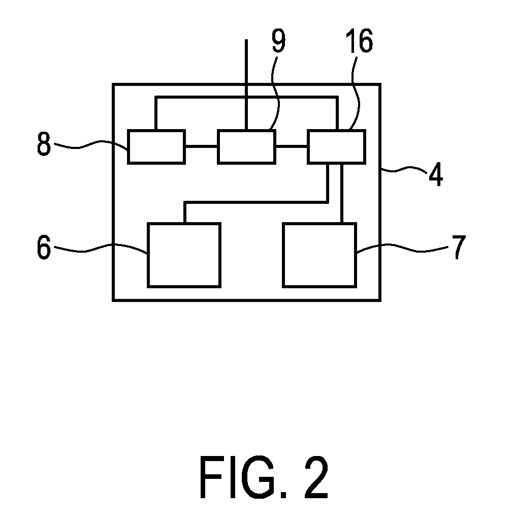
[0043]FIG. 2 shows schematically and exemplarily an embodiment of a PD 4...


PUM

PropertyMeasurementUnit
poweraaaaaaaaaa
standby poweraaaaaaaaaa

Abstract

The invention relates to a power distribution system (1), especially a Power-over-Ethernet system, comprising at least one dominant sensor, which may be located within a powered device (4) like a lighting device, and at least one non-dominant sensor, which may be located within another powered device (4), wherein the power distribution system is adapted such that in a system low power mode the at least one dominant sensor (6) consumes power provided by a power providing unit (3) and the at least one non-dominant sensor (6) does not consume the provided power and that the power distribution system (1) switches from the system low powermode to a system high power mode, if the at least one dominant sensor (6) has sensed an event. Since in the system low power mode the at least one non-dominant sensor does not consume power, the power consumption can be reduced.

Description

CROSS-REFERENCE TO PRIOR APPLICATIONS[0001]This application is the U.S. National Phase application under 35 U.S.C. § 371 International Application No. PCT / EP2015 / 050418, filed on Jan. 12, 2015, which claims the benefit of European Patent Application No. 14153436.2, filed on Jan. 31, 2014. These applications are hereby incorporated by reference herein.FIELD OF THE INVENTION[0002]The invention relates to a power distribution system, method and computer program for distributing power.BACKGROUND OF THE INVENTION[0003]A power distribution system in accordance with the Power-over-Ethernet (PoE) standard uses Ethernet cables for supplying direct current (DC) voltage from power supply equipment (PSE) to powered devices (PD) which may be lighting devices. The PoE power distribution system is often operable in a normal operation mode and in a standby mode, wherein even in the standby mode the power consumption within the PoE power distribution system can be relatively high.[0004]U.S. Pat. No....

Claims


Application Information

Patent Timeline
Patent Type & Authority Patents(United States)
IPC IPC(8): G05F1/66G06F1/18G05B13/02G05B19/042H04L12/28H05B37/02H04L12/12H02J3/14G05D3/12G05D5/00G05D9/00G05D11/00G05D17/00H04L12/10
CPCG05F1/66G05B13/0265G05B19/0428G06F1/189H04L12/10H04L12/12H05B37/0227H05B37/0254H04L12/2829Y04S20/228G05B2219/2642Y02B70/325Y02D50/40H05B47/18H05B47/105Y02D30/50H05B47/115Y02B20/40B01D53/228B01D67/0041B01D67/0046B01D67/0048B01D69/02B01D69/10B01D2325/20B01D2325/22B01D2325/28B01D2325/30B01J20/10B01J20/28004B01J20/28007B01J20/28033F17C11/00F17C11/007Y02B70/30Y04S20/20B01D69/106H02J2310/60G06F1/3206G06F1/3287
Inventor VAN ENDERT, TONY PETRUS
Owner SIGNIFY HLDG BV
Learn More