Tool pot

a technology for tools and pots, applied in the field of tools, can solve the problems of restricted thermal stress generation, and achieve the effects of not affecting the strength required for reinforcing the insertion portion of the mounting shaft, reducing the thermal contraction of the pot body, and avoiding the occurrence of thermal stress

Inactive Publication Date: 2018-10-09
OKUMA CORP
View PDF14 Cites 0 Cited by
  • Summary
  • Abstract
  • Description
  • Claims
  • Application Information

AI Technical Summary

Benefits of technology

[0008]It is an object of the invention to provide a tool pot having a metallic reinforcing member embedded in a resin-made pot body by insert molding, and having no probability of generation of fractures or cracks in a pot body caused by a thermal stress.
[0009]The invention provides a tool pot including a resin-made pot body and a metallic reinforcing member embedded in the pot body by insert molding, wherein the reinforcing member has a form which can be resiliently deformed without hindering thermal contraction of the pot body at the time of cooling after the insert molding.
[0010]With the tool pot of the invention, the resin-made pot body and the metallic reinforcing member tend to effect thermal contraction at the time of cooling after the insert molding. However, with the resilient deformation of the reinforcing member, hindrance of the thermal contraction of the pot body is avoided and hence generation of thermal stress is restricted.
[0012]With the tool pot having the above-described mode, generation of the thermal stress within the pot body is restricted by the lightening portion formed in the required position of the reinforcing member, and an influence exerted on a strength required for the reinforcing member is reduced.
[0014]In the case of the tool pot described above, the lightening hole is formed in the reinforcing plate of the reinforcing member so as to avoid the mounting shaft insertion portion, whereby the shape which allows the resilient deformation without hindering the thermal contraction of the pot body is achieved. Therefore, machining of the reinforcing member is easily and the strength required for reinforcing the mounting shaft insertion portion of the pot body is not hindered.
[0015]According to the tool pot of the invention, the strength of the metallic reinforcing member is enhanced, and generation of fractures or cracks in the resin-made pot body at the time of usage is avoided.

Problems solved by technology

However, with the resilient deformation of the reinforcing member, hindrance of the thermal contraction of the pot body is avoided and hence generation of thermal stress is restricted.

Method used


Image

  • Tool pot
  • Tool pot
  • Tool pot

Examples


Embodiment Construction

[0023]Subsequently, embodiments of the invention will be described with reference to FIG. 1 to FIG. 7.

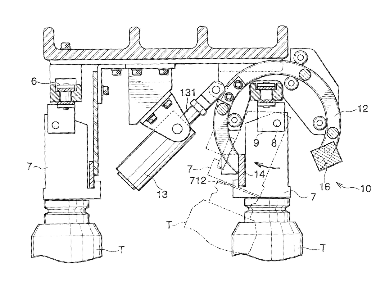
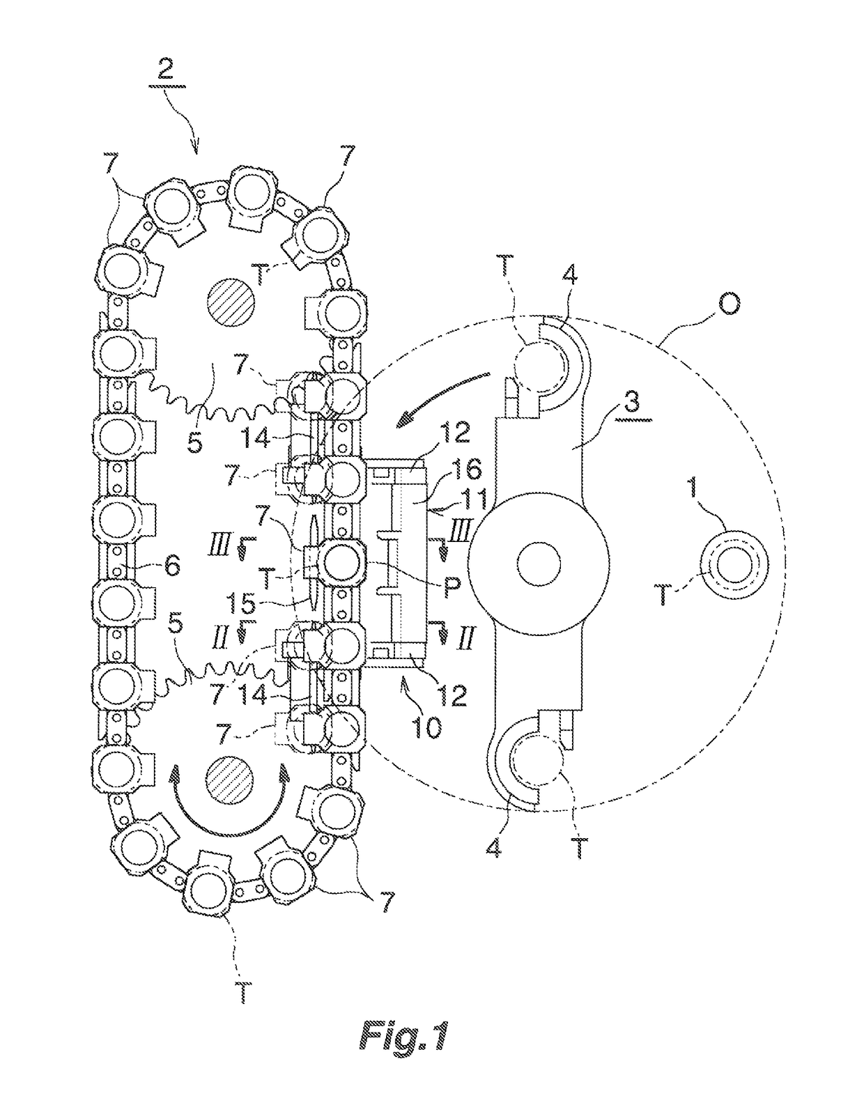
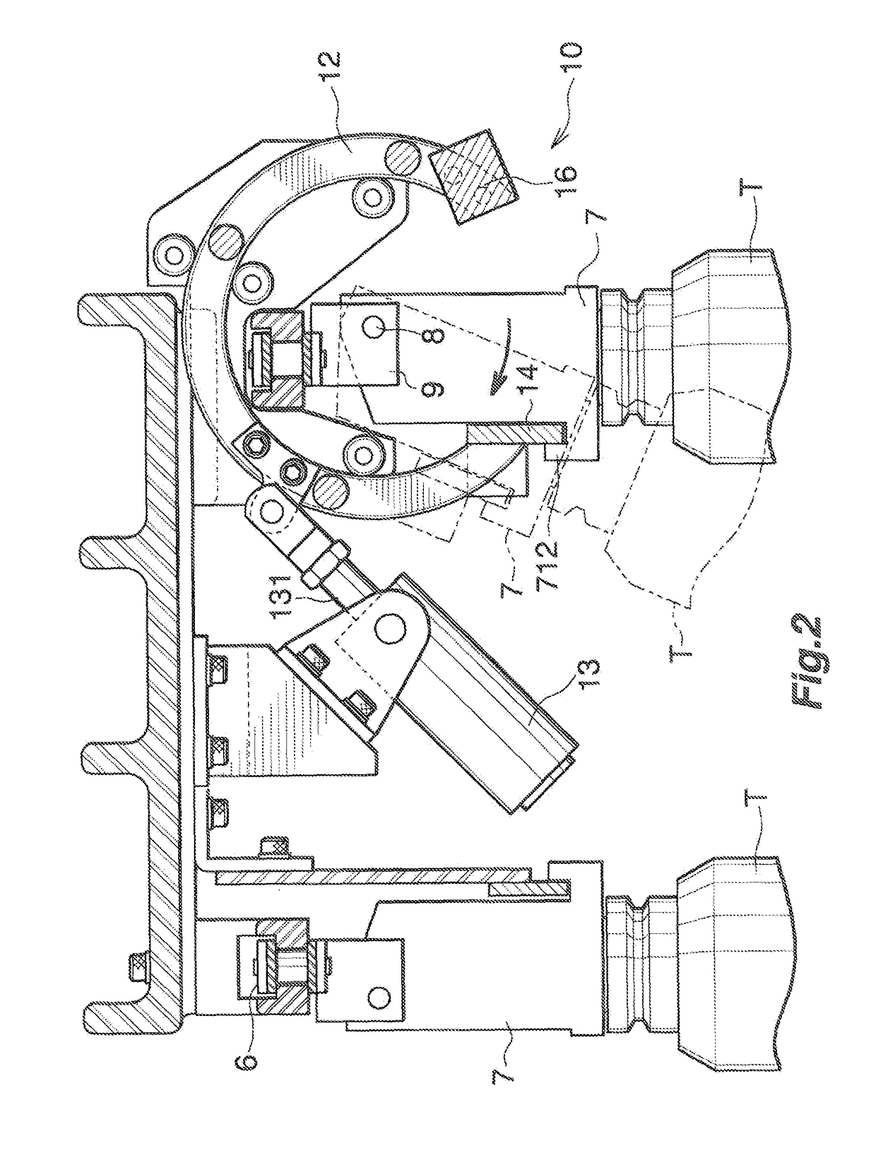
[0024]FIG. 1 to FIG. 3 illustrate an automatic tool replacing apparatus of a machining center provided with a tool pot, and FIG. 4 to FIG. 7 illustrate the tool pot of the invention in detail.

[0025]In the following description, an upper side of FIG. 1 corresponds to a “front”, and a lower side of the same correspond to a “rear”, and left and right of FIG. 1 corresponds to the “left and right”.

[0026]The automatic tool replacing apparatus illustrated in FIG. 1 to FIG. 3 is configured to exchange tools (T) automatically with respect to a main shaft (1) rotatably supported by a main shaft head of the machining center about a vertical axis, and includes a horizontal chain-type tool magazine (2) and a tool replacement arm (3) configured to be rotatable about the vertical axis and movable up and down to exchange tools (T) between the main shaft (1) and the tool magazine (2).

[0027]Grippers ...


PUM


Abstract

A tool pot includes a resin-made pot body and a metallic reinforcing member embedded in the pot body by insert molding. The reinforcing member is provided with a reinforcing plate embedded in a portion including a horizontal pin insertion portion in the pot body. The reinforcing plate is provided with a lightening hole so as to avoid the horizontal pin insertion portion.

Description

BACKGROUND OF THE INVENTION[0001]1. Field of the Invention[0002]The present invention relates to a tool pot used in a machine tool such as a machining center or the like for an apparatus configured to automatically exchange tools.[0003]2. Description of the Background Art[0004]In a machine tool such as a machining center, if the number of tools required for machining a work, a stocker such as a tool magazine is installed in addition to a machine tool to hand over the tools between the machine tool and the stocker. When retaining the tools in the tool magazine, which corresponds to the stocker, a tool pot configured to house and retain the tools so as to be demountably mountable is used (For example, see JP-A-2002-126961).[0005]The tool pot is generally formed of a resin mold, which is low in manufacturing costs and is produced on a large scale because a number of the tool pots having the same form are used. However, in the case of the tool pot formed of the resin mold, for example, ...

Claims


Application Information

Patent Timeline
Patent Type & Authority Patents(United States)
IPC IPC(8): B23Q3/155B23Q3/157
CPCB23Q3/15526B23Q3/15553B23Q3/1572Y10T483/1891Y10T483/1836Y10T483/1864B23Q2003/15532B23Q3/15724B23Q2003/15527
Inventor KAWADA, NAOKI
Owner OKUMA CORP
Why Eureka
Try Eureka