Fuel injector for operation with combustible gas

Active Publication Date: 2018-09-25
L'ORANGE GMBH
View PDF25 Cites 1 Cited by
  • Summary
  • Abstract
  • Description
  • Claims
  • Application Information

AI Technical Summary

Benefits of technology

The present invention proposes a fuel injector that helps minimize the flow of combustible gas and reduces flow losses. This is achieved by designing a holder with a non-symmetrical cross-section, which allows for a greater cross-section for the gas flow opposite the nozzle openings. The cross-section widening is guided along a flow path without stepped falls, which helps guide more gas into the combustion chamber with higher engine power. The nozzle-side end portion of the gas nozzle needle is asymmetrically formed to further minimize flow losses. The gas nozzle needle is also configured bulging to improve flow and retain pulse retention. The invention also allows for a line of sight or sight channel from the outlet end of the cross-section widening to the inlet cross-section of the gas nozzle opening, without the need for a flow-disruptive deflection of the combustible gas flow.

Problems solved by technology

However, such fuel injectors, the nozzle needles of which are received as standard in respective rotationally symmetrical bores, entail the disadvantage that flow losses of combustible gas occur because of the asymmetric flow around the needle seat.

Method used


Image

  • Fuel injector for operation with combustible gas
  • Fuel injector for operation with combustible gas
  • Fuel injector for operation with combustible gas

Examples


Embodiment Construction

[0028]In the description which follows and in the drawings, the same reference signs correspond to elements with the same or equivalent function.

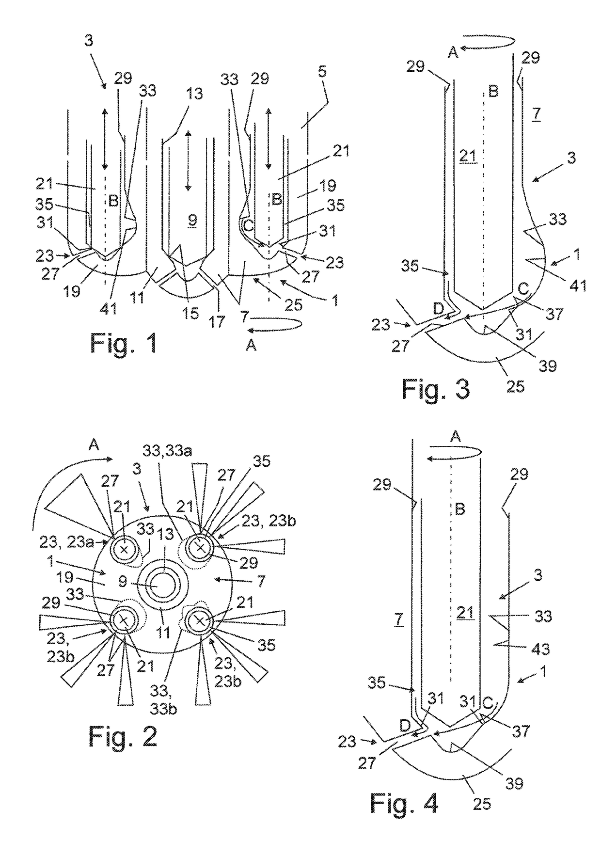
[0029]FIG. 1 shows diagrammatically as an example a nozzle-side end portion 1 of a fuel injector 3 according to the invention for operation with combustible gas, wherein the fuel injector 3 illustrated is provided as a dual-fuel injector, i.e. for operation both with liquid fuel and also with combustible gas. The liquid fuel for use with the fuel injector 3 may be diesel fuel, bio-oil, fuel oil or another type of liquid fuel, as combustible gas for use with the fuel injector 3, in particular natural gas, e.g. also biogas, landfill gas etc. may be used. The fuel injector 3 provided in this way is intended in particular for an ignition jet operation and also for example with a purely liquid fuel operation.

[0030]The fuel injector 3 has an injector housing 5 which is formed with a nozzle body 7, in the present case in particular by means of a m...


PUM


Abstract

A fuel injector for operation with combustible gas, having a gas nozzle assembly having at least one gas nozzle opening, and at least one gas nozzle needle associated with the gas nozzle assembly and accommodated in an axial holder so that the stroke of the gas nozzle needle can be controlled. Each gas nozzle opening leads out of the holder having a radial direction component at the nozzle end. The fuel injector has, in the holder, a needle seat upstream of the particular nozzle opening, which needle seat is provided for selectively blocking a combustible-gas flow path to the associated gas nozzle opening in interaction with the gas nozzle needle. The gas nozzle openings are distributed over part of the circumference in the circumferential direction of the gas nozzle needle. The holder, adjoining the needle seat and extending away therefrom axially in the upstream direction, is asymmetric with respect to an axial center axis through the gas nozzle needle. The asymmetry results from a cross-section expansion of the holder on a side of the holder that lies radially opposite the gas nozzle opening, such that a greater mass flow rate of combustible gas can be conducted in the holder by the crosssection expansion than on the gas nozzle opening side opposite thereto. The holder is also shaped to apply a flow direction oriented toward the radially opposite gas nozzle opening, already upstream of the needle seat and via the cross-section expansion, to a combustible-gas flow guided to the needle seat by the cross-section expansion.

Description

[0001]The present application is a 371 of International application PCT / EP2016 / 000018, filed Jan. 7, 2016, which claims priority of DE 10 2015 001 199.5, filed Jan. 31, 2015, the priority of these applications is hereby claimed and these applications are incorporated herein by reference.BACKGROUND OF THE INVENTION[0002]The present invention concerns a fuel injector for operation with combustible gas. The fuel injector may in particular be formed as a dual-fuel injector.[0003]Gaseous fuels are increasingly gaining importance in the (large) engine sector, in particular in stationary engines for power generation. Natural gas for example, because of its excellent availability and favorable emission potential in comparison with diesel fuel, is ideally suited for economic and environmentally friendly engine operation.[0004]In fuel injectors which are formed as multiple substance injectors or dual-fuel injectors, and as well as the gas injector part also comprise a liquid fuel injector par...

Claims


Application Information

Patent Timeline
IPC IPC(8): F02B3/00F02M21/02F02M43/04
CPCF02M21/0263F02M43/04F02M21/0284F02M21/0275F02M2200/44Y02T10/30
Inventor BERGER, INGMAR JOACHIMKALENBORN, MARKUS
Owner L'ORANGE GMBH
Why Eureka
Try Eureka