
Valve structure for propane tank and method thereof

a valve structure and propane tank technology, applied in the direction of vessel construction details, container discharging methods, mechanical devices, etc., can solve the problems of difficulty and time-consuming to reset the cooking station, and the flow limiting device is often unnecessarily triggered

Pending Publication Date: 2022-04-21
NORTH ATLANTIC IMPORTS
View PDF12 Cites 0 Cited by
  • Summary
  • Abstract
  • Description
  • Claims
  • Application Information

AI Technical Summary

Benefits of technology

This patent describes a method and device for controlling the flow of gas from a propane tank. The device includes a plug that can be opened and closed to control the gas flow. The plug has a tapered portion that helps to minimize gas flow initially to prevent the device from being tripped. The device can also include a flow limiting device with a blocking component that can be moved to a blocking position when the gas flow rate exceeds a predetermined level. The method involves maintaining the gas in the tank and then opening the plug to allow the gas to flow through the flow limiting device and into a desired delivery system. The device helps to control the flow rate and prevent the blocking component from being moved to the blocking position. This invention helps to safely and accurately control the delivery of propane gas.

Problems solved by technology

Once the flow limiting devices are triggered to minimize the gas flow, it can be difficult and time consuming to reset the cooking station to establish or re-establish appropriate gas flow to the cooking station.
Additionally, it has been found that flow limiting devices often are unnecessarily triggered when initially opening the valve of the propane tank.

Method used


Image

  • Valve structure for propane tank and method thereof
  • Valve structure for propane tank and method thereof
  • Valve structure for propane tank and method thereof

Examples


Embodiment Construction

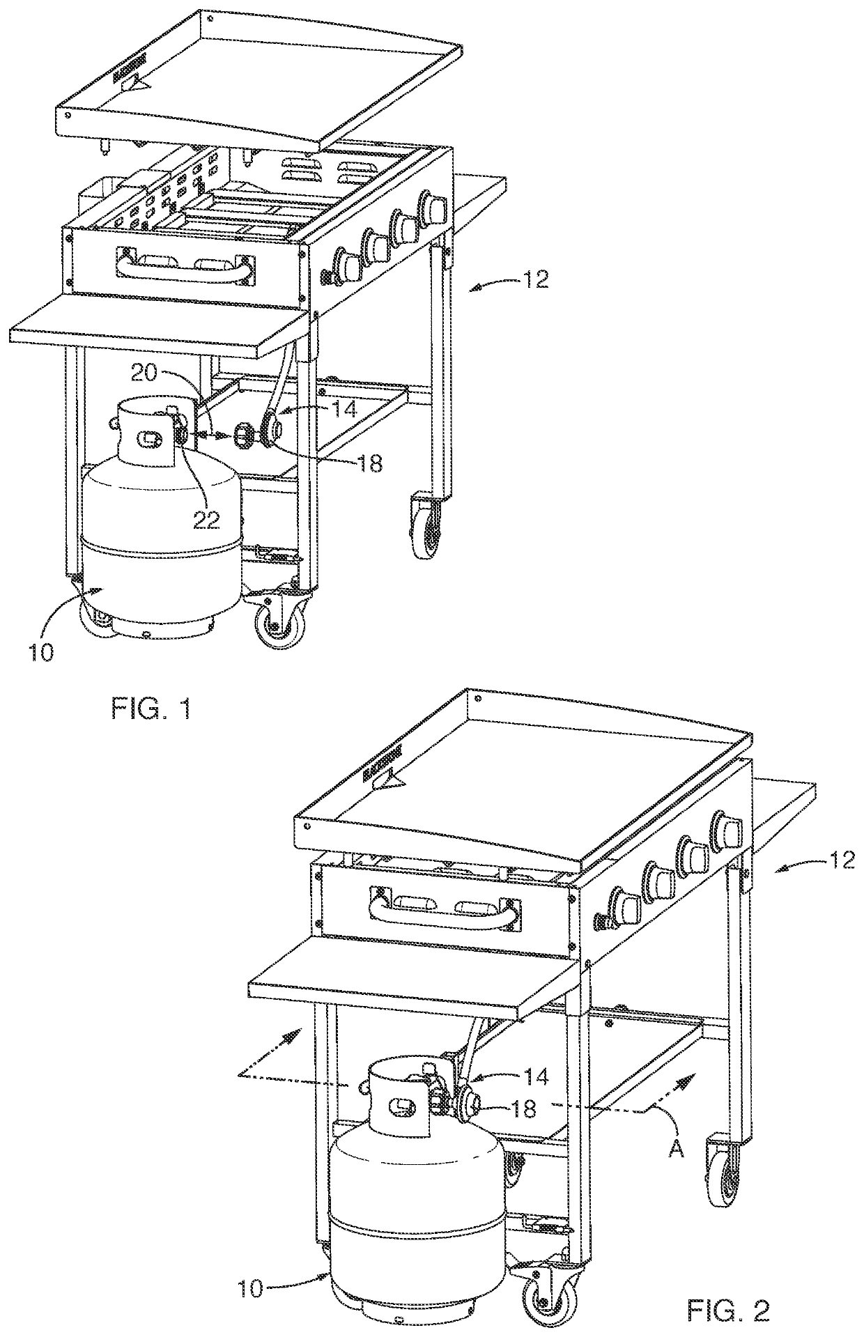
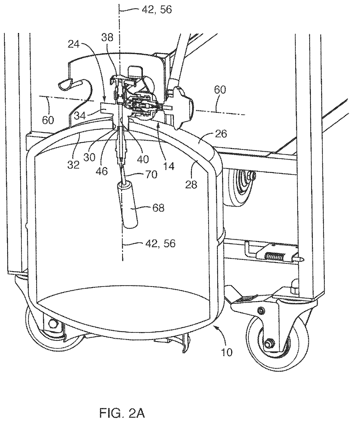
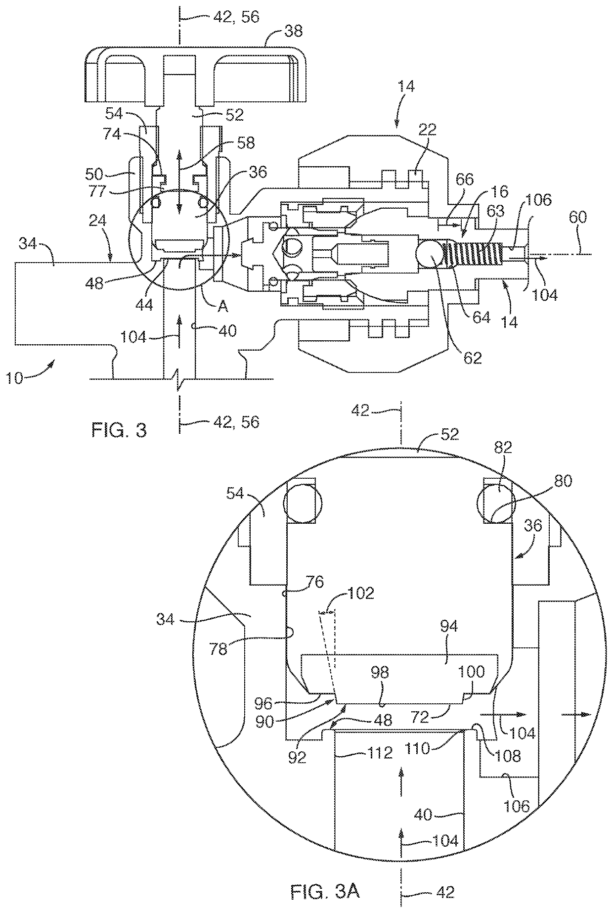
[0024]Referring to FIGS. 1, 2 and 3, a propane tank 10 sized and configured to hold propane gas is provided. The propane tank 10 may be employed with a cooking station 12, such as a grill or griddle type cooking station, or other devices that may utilize propane gas as a fuel. The propane tank 10 may be coupled to the cooking station 12 with a flow limiting device 14 therebetween, for safety reasons. For example, the flow limiting device 14 may include a tripping component 16 that closes-off or blocks the flow of propane gas through the flow limiting device 14 upon there being a sudden change in the flow rate passing through the flow limiting device 14. Further, the flow limiting device 14 includes a pressure regulator 18 associated therewith that limits the fuel pressure moving through the flow limiting device 14 to a predetermined pressure level. As shown by bidirectional arrow 20, the propane tank 10 may include a coupling member 22 sized and configured to be coupled to, or decou...


PUM

PropertyMeasurementUnit
Flow rateaaaaaaaaaa

Abstract

Embodiments of a propane tank valve are provided. In one embodiment, the propane tank valve includes a plug with a tapered portion, the plug moveable between closed and open positions relative to a valve passageway. Upon the plug being in the closed position, the tapered portion of the plug is positioned within the valve passageway. Upon the plug being initially moved from the closed position to the open position, the tapered portion of the plug is sized and configured to initially minimize the gas flow from the valve passageway and through a flow limiting device configured to be coupled to the propane tank valve such that movement of the tapered portion from the closed plug position initially forms a gap between a tapered surface of the tapered portion and an internal surface of the valve passageway.

Description

CROSS-REFERENCE TO RELATED APPLICATIONS[0001]This application claims the benefit of U.S. Provisional Application No. 63 / 092,380, filed Oct. 15, 2020, the disclosure of which is hereby incorporated by reference herein in its entirety.TECHNICAL FIELD[0002]The present invention relates generally to propane gas valves and, more specifically, the present invention relates to propane gas valves for controlling gas flow therefrom.BACKGROUND[0003]Barbequing has become a popular and pervasive tradition in much of the world. A barbeque grill is a device for cooking food by applying heat to a cooking surface, such as a grill or a griddle type of outdoor cooking station. Often the heating of outdoor cooking stations is employed with propane gas supplied from a propane gas tank. For safety reasons, it is required to include a flow limiting device in-line between the propane gas tank and its associated cooking station. Flow limiting devices are employed so that if the gas flow progresses above a ...

Claims


Application Information

Patent Timeline
IPC IPC(8): F16K1/30
CPCF16K1/305F17C13/04F16K1/54F17C2201/0109F17C2201/032F17C2201/056F17C2201/058F17C2203/0617F17C2205/0329F17C2205/035F17C2205/0385F17C2221/035F17C2223/0153F17C2223/033F17C2270/0709F17C2250/0413F17C2205/0338F17C2203/0639F17C2203/0643F17C2203/0646F17C2203/0648F17C2203/066
Inventor GRAHAM, GARY E.
Owner NORTH ATLANTIC IMPORTS
Learn More