
Optical sheet and method for manufacturing same

a technology of optical sheets and fine grooves, applied in the field of optical sheets, can solve the problems of peel marks, thermoplastic resin is not sufficiently solidified and cooled, and the transfer property of the fine groove structure is likely to deteriorate, so as to prevent the cooling of resin, improve the transfer property of the fine groove structure, and enhance the transfer rate

Active Publication Date: 2018-09-04
MITSUBISHI GAS CHEM CO INC +1
View PDF16 Cites 0 Cited by
  • Summary
  • Abstract
  • Description
  • Claims
  • Application Information

AI Technical Summary

Benefits of technology

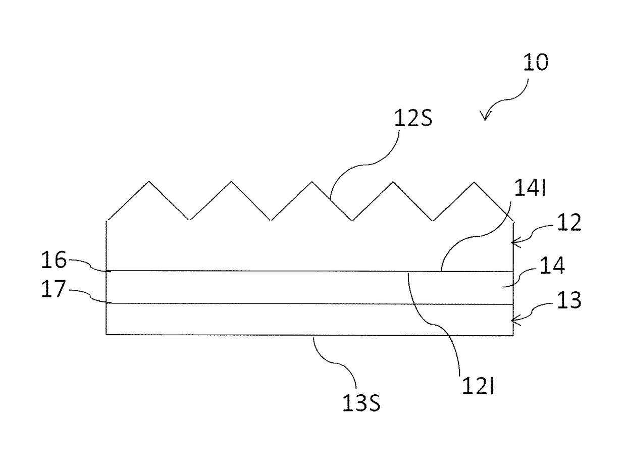
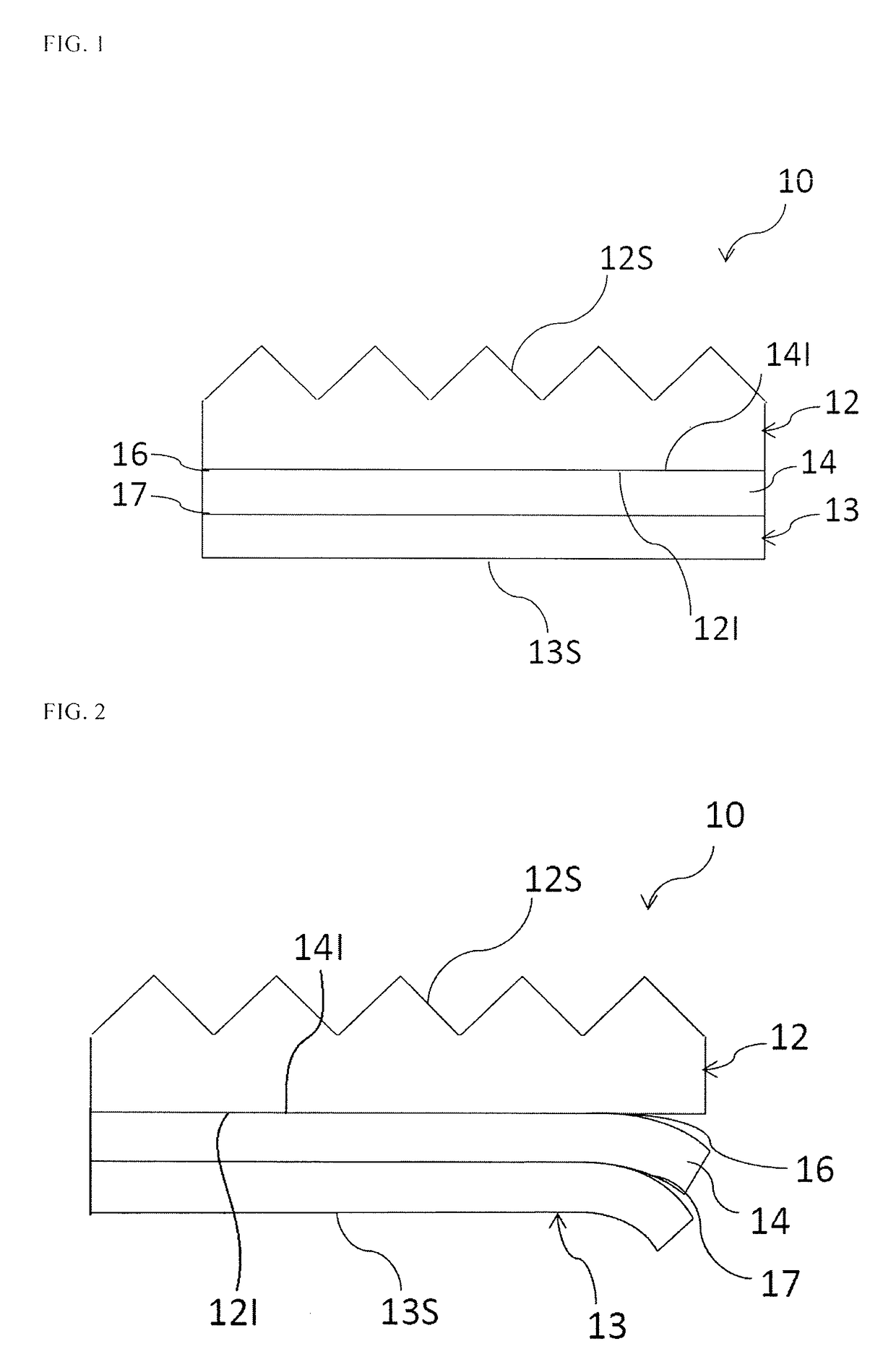
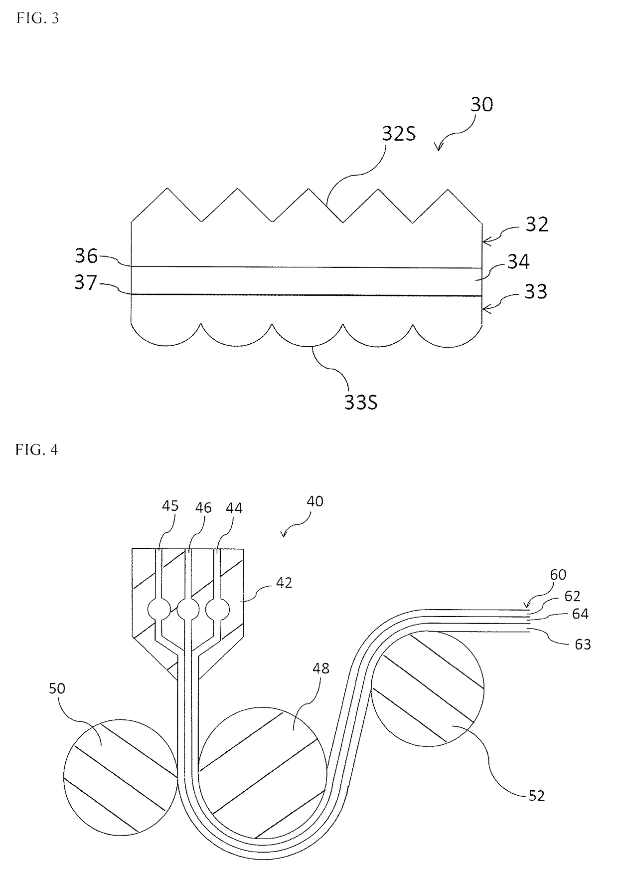
[0016]An optical sheet of the present invention is an optical sheet that is obtained by laminating a first layer comprising a polycarbonate resin, a second layer comprising a polyamide resin and a third layer by coextrusion molding, wherein: the second layer is laminated between the first layer and the third layer; the first layer and the second layer, and the second layer and the third layer are peelable at their interfaces, respectively; and a fine grooved shape is formed on the outer surface of the first layer. Since the total thickness of the optical sheet having these multiple layers can be made thick upon melt extrusion molding, i.e., upon transfer of the fine grooved structure, a sufficient amount of heat can be retained in the laminated body during molding so that rapid cooling of the resin is prevented in the air gap region and while being pressed between the rolls, thereby remarkably improving the transfer property of the fine grooved structure. Furthermore, since there is no need to set the temperature specially high upon molding in order to enhance the transfer rate, good appearance of the molded sheet can easily be maintained. In addition, since the first layer comprising the polycarbonate resin and the second layer comprising the polyamide resin can easily be separated from each other by peeling after the coextrusion molding, an eventually (i.e., by the peeling apart the laminated body) very thin optical sheet can be molded, in spite of the high transfer rate of the fine grooved structure. Furthermore, in a case where a set of cooling / shaping rolls each having a fine grooved structure on its surface are used for sandwiching a sheet under pressure, two optical sheets can be obtained from the first layer and the third layer through a single molding.
[0017]Additionally, since the polycarbonate resin and the polyamide resin have moderate peel strength, no peeling is caused at the interface during coextrusion molding for making them into a sheet. Moreover, if, for example, the polyamide resin is amorphous and the difference of the glass transition temperature from that of the polycarbonate resin is within ±40° C., the molding shrinkage can be made almost equal to that of the polycarbonate resin and thus problems such as warpage are not caused.
[0018]In addition, the resin of the second layer or the resins of the second and third layers that are used in order to increase the thickness of the laminated body upon coextrusion molding but are not used as the eventual optical sheet after being peeled off may be collected and reused. Accordingly, recycled materials of the polycarbonate resin and the polyamide resin may be used in the first place as the resin layers that are not utilized as the optical sheet.
[0019]Moreover, since recycled materials can be used as described above, the present invention is also capable of reducing the cost for manufacturing an optical sheet.

Problems solved by technology

In general, the thinner the sheet is, the more the transfer property of the fine grooved structure is likely to deteriorate.
However, if the set temperatures of the die and the roll are too high, the thermoplastic resin is not sufficiently solidified and cooled as the sheet is pressed between the cooling / shaping roll and the press roll and peeled off from the cooling / shaping roll.
As a result, the molded sheet sticks to the cooling / shaping roll, causing an appearance defect called peel marks.
In addition, if the pressing pressure is raised too much, roll bending occurs due to lack of roll rigidity which results in defects such as difficulty in controlling the film thickness of the molded sheet or difficulty in uniform transfer.

Method used


Image

  • Optical sheet and method for manufacturing same
  • Optical sheet and method for manufacturing same
  • Optical sheet and method for manufacturing same

Examples


example 1

[0094]In Example 1, Iupilon S-3000N (aromatic polycarbonate; Tg: 145° C.) from Mitsubishi Engineering-Plastics Corporation was used as a polycarbonate resin while an amorphous polyamide resin Grilamid TR XE 3805 (Tg: 153° C.) from EMS was used as a polyamide resin. The amorphous polyamide resin was plasticized by a 75 mmφ vent-type single-screw extruder while the polycarbonate resin was plasticized by a 40 mmφ vent-type single-screw extruder and a 32 mmφ vent-type single-screw extruder, respectively, and laminated using a 800-mm-wide multi-manifold die (see die 42 in FIG. 4) set at 280° C. to be extruded as a sheet. The above-described laminated body was molded to make a layered structure of the polycarbonate resin I (32 mmφ vent-type single-screw extruder), the amorphous polyamide resin (75 mmφ vent-type single-screw extruder) and the polycarbonate resin II (40 mmφ vent-type single-screw extruder) sequentially from the upstream side. The sheet-like molten resin flowing out from the...

example 2

[0101]In Example 2, sheet forming was performed in exactly the same manner as Example 1 except that: the grade of the polycarbonate resin was changed to Iupilon H-4000N from Mitsubishi Engineering-Plastics Corporation (a bisphenol A aromatic polycarbonate obtained by polymerizing bisphenol A and phosgene through interfacial polycondensation, with a viscosity average molecular weight [Mv] of about 15000 and Tg of 140° C.); the type of the polyamide resin was changed to a polyamide resin Grivory G-21 from EMS (an amorphous polyamide resin, a mixture of Nylon (registered trademark) 6T (hexamethylene diamine+terephthalic acid) and Nylon (registered trademark) 6I (hexamethylene diamine+isophthalic acid), and made amorphous owing to an increase in the randomness of the molecular structure of crystalline PA). Tg: 125° C.); the thickness of the polycarbonate resin layer I was changed to 75 μm; the thickness of the polyamide resin layer was changed to about 150 μm; and the metal pressing / coo...

example 3

[0106]In Example 3, a crystalline polyamide resin UBE Nylon 1030B from Ube Industries, Ltd. was used as the polyamide resin to mold a prism sheet with a thickness of about 75 μm. The primary molding conditions were generally the same as Example 1. The transfer rate of this prism sheet was 74%.


PUM

PropertyMeasurementUnit
thicknessaaaaaaaaaa
glass transition temperatureaaaaaaaaaa
thicknessaaaaaaaaaa

Abstract

An optical sheet is formed by laminating, by co-extrusion molding, a first layer containing a polycarbonate resin, a second layer containing a polyamide resin, and a third layer, wherein the second layer is laminated between the first layer and the third layer, the first layer and second layer, and the second layer and third layer can each be peeled at the interface, and the outer surface of the first layer has a fine grooved structure. The optical sheet, which is provided with a plurality of layers in such a way, is capable of retaining, a sufficient amount of heat in a laminate in a mold since the entire sheet can be made thick during melt extrusion molding, and is able to improve the transferability of the fine grooved structure. In addition, the optical sheet can be made thinner by using only the peeled first layer as an optical sheet.

Description

TECHNICAL FIELD[0001]The present invention relates to an optical sheet and a method for manufacturing the same. The optical sheet of the present invention can preferably be used for enhancing luminance and improving viewing angles of various display devices including television, and various display devices for, for example, lighting equipments and digital signage.BACKGROUND ART[0002]When a thermoplastic resin sheet is molded by melt extrusion, a cooling / shaping roll that has a fine grooved structure on its surface is often used to transfer said fine grooved structure onto the sheet surface, thereby imparting various functions onto the surface of the molded sheet made from the thermoplastic resin. For example, a roll having a fine prism structure on its surface is used to transfer said prism structure onto a sheet to manufacture a highly functional luminance enhancement sheet by melt extrusion molding.[0003]In order to mold such a sheet by melt extrusion, generally, a sheet of a molt...

Claims


Application Information

Patent Timeline
Patent Type & Authority Patents(United States)
IPC IPC(8): G02B6/10B29D7/01B32B7/06G02B5/02G02B1/04B32B7/027
CPCG02B5/021B29D7/01B32B7/06G02B1/04B32B2307/40B32B27/34B32B27/36B32B3/30G02B3/00G02B5/02B32B27/08B32B27/18B32B27/20B32B27/308B32B27/365B32B2250/03B32B2250/24B32B2250/40B32B2270/00B32B2272/00B32B2274/00B32B2307/30B32B2307/4026B32B2307/408B32B2307/412B32B2307/702B32B2307/704B32B2307/732B32B2307/734B32B2307/738B32B2307/748B32B2457/20B32B2509/00B32B2551/00B29C48/08B29C48/21B29C48/23B32B7/027G02B3/0062G02B5/0215
Inventor KAKINOKI, OSAMUTAKEDA, MASAHIDEOHNO, SHOTAROONISHI, TAKESHISUGIYAMA, MASATAKA
Owner MITSUBISHI GAS CHEM CO INC
Learn More