
Constant impedance connector system for quantum computer applications

Active Publication Date: 2018-08-14
THE PHOENIX OF CHICAGO
View PDF11 Cites 8 Cited by
  • Summary
  • Abstract
  • Description
  • Claims
  • Application Information

AI Technical Summary

Benefits of technology

The present invention aims to address various technical issues in a cryogenic environment. Its first technical effect is to reduce thermal energy resulting from transmitted signal power. Its second technical effect is to provide a connection system that can be easily assembled without damage to the extremely small diameter center conductors of the cabling. The third technical effect is to accommodate system electrical filtering in a cryogenic environment to reduce extraneous electrical signals (noise) coupled onto conductors.

Problems solved by technology

The drawbacks of cryogenic operation include: the necessity for an appropriate cooling system; the selection of materials and components optimized for low temperature operation; and, interfacing aspects between “cold” and “warm” electronics, among others.

Method used


Image

  • Constant impedance connector system for quantum computer applications
  • Constant impedance connector system for quantum computer applications
  • Constant impedance connector system for quantum computer applications

Examples


first embodiment

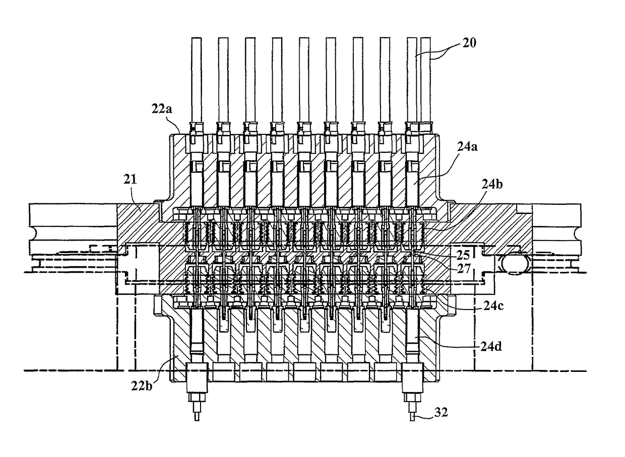
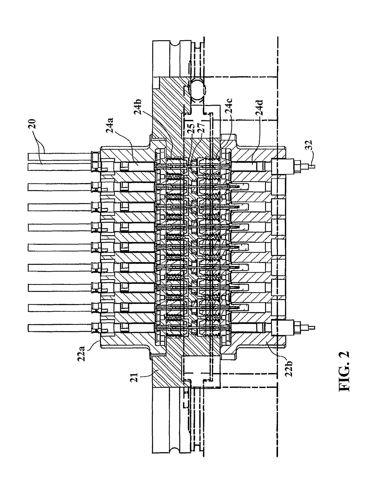
[0040]As will be discussed in further detail below, the modification of the constant impedance connection may be presented in different distinct designs and at different stages. For example, in a first embodiment, an attenuator or filter is embedded in either a constant impedance connector receptacle or plug. As depicted in FIG. 4, the connector receptacle is installed into a receptacle housing block 9a, and the connector plug is installed into a plug housing block 9b, such that when the receptacle housing block 9a is mated to the plug housing block 9b, the receptacle and plug connectors are mated as well. This allows for proper alignment of the contacts and thermal dissipation through the housing blocks.

second embodiment

[0041]In a second embodiment an attenuator component or filter component adaptor is employed within its own adapter body which is then mounted into an adaptor housing, which preferably accommodates a plurality of adaptor bodies. The adaptor housing is then mounted to a plate, such as a refrigeration plate. The adaptor housing will receive on one side connectors from a receptacle housing block, and on the other side connectors from a plug housing block. It is also possible for an adaptor housing to be designed to receive connectors from a receptacle housing block on both sides, or connectors from a plug housing block on both sides, such that, in either embodiment, a constant impedance connection is made on each side of the adaptor housing.

[0042]The attenuator lowers the power on each center conductor without changing the signal integrity. In cooling applications, the excess thermal energy from the attenuated signals is then dissipated through the housing to a heat sink, such as refri...


PUM


Abstract

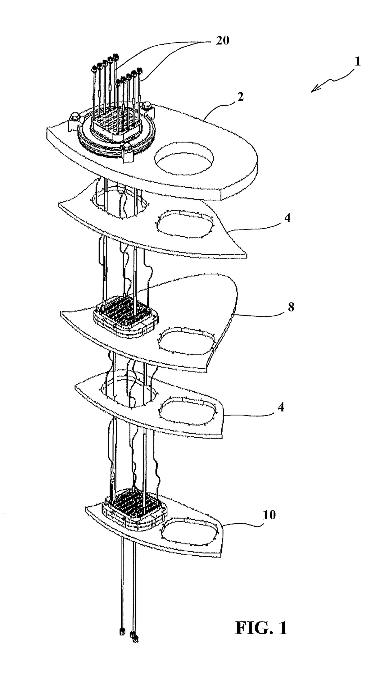
A connection system for a quantum computer that employs constant impedance connectors with attenuation or filtering components or both embedded therein or within an adaptor removably insertable within an adaptor housing for use in a cryogenically cooled quantum computer. The connection system provides a higher density of cables traversing through a hermetic sealed top plate, and which are accessible to chill blocks to reduce the thermal energy from the signal lines. Attenuators or filter circuits are embedded in the constant impedance connector housings, or provided in adaptors that connect on each end to form mating constant impedance connections, in order to reduce signal strength as the signal progresses through the cryogenic environment and to remove extraneous electrical signal noise.

Description

BACKGROUND OF THE INVENTION1. Field of the Invention[0001]The present invention relates to computer technology, and specifically to the connection system for a quantum computer. More specifically, the present invention relates to a constant impedance connector system, utilizing the characteristics of known constant impedance connectors, some with embedded attenuation and / or filtering components, for use in a cryogenically cooled quantum computer, and some that are in the form of adapters having constant impedance connections.2. Description of Related Art[0002]Today's computer work by manipulating bits that exist in one of two states: a 0 or a 1. Quantum computers, however, are not limited to two states; they encode information as quantum bits, or qubits, which can exist in superposition. Qubits represent atoms, ions, photons, or electrons and their respective control devices that are working together to act as computer memory and / or a processor. Because a quantum computer can contai...

Claims


Application Information

Patent Timeline
IPC IPC(8): H01R9/05H01B7/29G06N99/00B82Y10/00
CPCH01B7/29G06N99/002B82Y10/00H01R13/521H01R24/42G06N10/00
Inventor MATURO, JOHN E.BRADLEY, ROBERT M.
Owner THE PHOENIX OF CHICAGO
Learn More