
Parking and location determination on-vehicle device

a technology for location determination and vehicle, applied in vehicle components, location information based services, network topologies, etc., can solve the problems of useless waste of power of on-vehicle device and mobile terminal, and achieve the effect of reducing power waste, narrowing the communication range, and reducing useless communication connections

Active Publication Date: 2018-07-31
DENSO CORP
View PDF23 Cites 0 Cited by
  • Summary
  • Abstract
  • Description
  • Claims
  • Application Information

AI Technical Summary

Benefits of technology

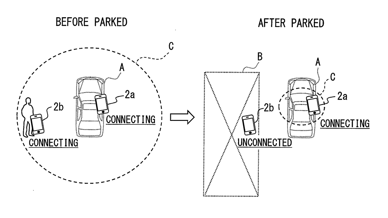
The patent aims to reduce power waste in wireless communication between a mobile device and an on-vehicle device using a narrowed communication range when the vehicle is parked. This helps prevent unwanted connections and reduces power waste, making it more efficient and effective for providing on-vehicle services to users via wireless communication.

Problems solved by technology

When a communication connection is established between an on-vehicle device and a mobile terminal even in a situation where the communication connection is not intended by the user, the power of the on-vehicle device and the mobile terminal is uselessly wasted.

Method used


Image

  • Parking and location determination on-vehicle device
  • Parking and location determination on-vehicle device
  • Parking and location determination on-vehicle device

Examples


first embodiment

[0018](First Embodiment)

[0019]100>

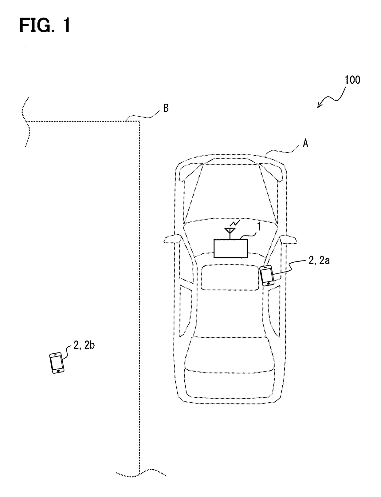
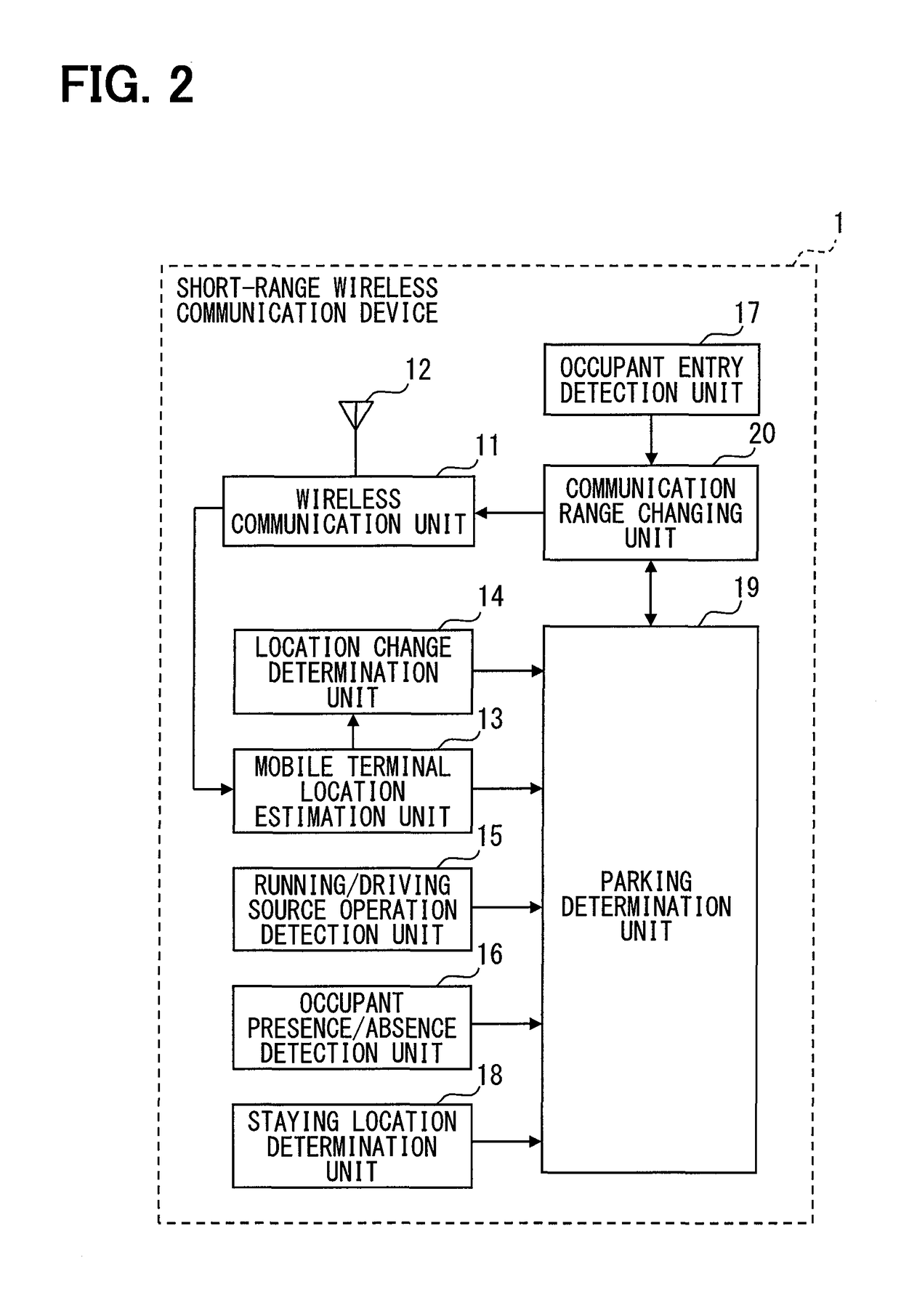
[0020]An embodiment of the present disclosure will be described with reference to the drawings. FIG. 1 is a view showing an example of a schematic configuration of a short-range wireless communication system 100 to which the present disclosure is applied. As shown in FIG. 1, the short-range wireless communication system 100 includes a short-range wireless communication device 1 mounted on a vehicle A, a mobile terminal 2a, and a mobile terminal 2b.

[0021]The mobile terminals 2a and 2b are mobile terminals such as a multifunctional mobile phone that can be carried or brought along by a user. The mobile terminal 2a is located in the interior of the vehicle A. The mobile terminal 2b is located at a place away from the vehicle A, such as in a room in a building B. By way of example, it is assumed that the mobile terminals 2a and 2b are identical mobile terminals except that the locations thereof relative to the short-range wireless communication device ...

first modification

[0061](First Modification)

[0062]The first embodiment has shown the configuration which changes the communication range of the wireless communication unit 11 between the wide communication range and the narrow communication range at two levels. However, the configuration is not necessarily limited thereto. For example, the communication range of the wireless communication unit 11 may be categorized into a plurality of levels more than two levels, and be changed stepwise from one of the levels to another (hereinafter referred to as a first modification).

[0063]The following will describe the first modification using the drawings. Note that, for the convenience of description, in the description of the first modification and subsequent description, members having the same functions as those of the members shown in the drawings used for the previous description shall be given the same reference numerals and a description thereof is omitted. The short-range wireless communication device 1...

second modification

[0074](Second Modification)

[0075]indifferently from the first modification, such a configuration may also be adopted in which, when the communication range of the wireless communication unit 11 is stepwise narrowed, the communication range is stepwise narrowed in another form such that the communication range is stepwise narrowed every time a given time period elapses.


PUM


Abstract

An on-vehicle device, which is to be mounted on a vehicle, includes a wireless communication unit which is connected to a mobile terminal located within a communication range to perform wireless communication with the mobile terminal, and provides a service using the wireless communication in the wireless communication unit. The on-vehicle device further includes a parking determination unit which determines whether or not the vehicle is parked and a communication range changing unit which narrows, when the parking determination unit determines that the vehicle is parked, the communication range of the wireless communication unit such that the communication range is narrower than that before the parking determination unit determines that the vehicle is parked.

Description

CROSS REFERENCE TO RELATED APPLICATIONS[0001]This application is a U.S. National Phase Application under 35 U.S.C. 371 of International Application No. PCT / JP2016 / 000844 filed on Feb. 18, 2016 and published in Japanese as WO 2016 / 143269 A1 on Sep. 15, 2016. This application is based on and claims the benefit of priority from Japanese Patent Application No. 2015-045149 filed on Mar. 6, 2015. The entire disclosures of all of the above applications are incorporated herein by reference.TECHNICAL FIELD[0002]The present disclosure relates to an on-vehicle device which performs wireless communication with a mobile terminal.BACKGROUND ART[0003]As described in Patent Literature 1, a technique has been known which allows a user to receive various services such as a hands-free phone call using wireless communication between a mobile terminal carried by the user and an on-vehicle device mounted on a vehicle. In general, an on-vehicle device which performs wireless communication with a mobile te...

Claims


Application Information

Patent Timeline
Patent Type & Authority Patents(United States)
IPC IPC(8): H04W24/00H04W52/28H04W24/02H04W84/12H04W4/029H04W4/40H04W4/48
CPCH04W52/28H04W4/40H04W24/02H04W84/12H04W4/027H04W4/023H04W4/48H04W4/029
Inventor MATSUSHITA, SUGURU
Owner DENSO CORP
Learn More