Liquid separator for an evaporator system

a technology of liquid separator and evaporator, which is applied in the direction of refrigeration components, lighting and heating apparatus, refrigeration machines, etc., can solve the problems of difficult connection of two or more evaporators or evaporators with double exits, short and bulky with a large diameter, and high pressure drop

Active Publication Date: 2018-07-31
ALFA LAVAL CORP AB
View PDF47 Cites 0 Cited by
  • Summary
  • Abstract
  • Description
  • Claims
  • Application Information

AI Technical Summary

Benefits of technology

[0040]The object of the present invention is to eliminate or at least alleviate the above referenced drawbacks and limitations of the present evaporator separators. The separator is designed as a U-shaped pipe comprising two essentially parallel pipes interconnected by means of a pipe portion, said pipes being arranged essentially horizontally.
[0041]By the present invention an evaporator separator has been achieved which makes the overall evaporator system more compact and less space consuming as well as at the same time making the separation more efficient. The compact design of the separator is also beneficial for economic reason.
[0042]Due to the small diameter of the separator pipes the weight of the separator is reduced. The smaller size of the separator makes it possible to utilize materials of higher grade and still achieve an economic solution. In this way surface coating against corrosion may be avoided and costs lowered. The small diameters allows for standard pipe components accessible on the market to be used rather than specifically tailor made components.
[0043]Furthermore, the refrigerant charge to the separator is reduced and accordingly the environmental and personal safety is enhanced.

Problems solved by technology

Separation is very effective, but the pressure drop is also very high.It is difficult to connect two or more evaporators or an evaporator with double exits.
A traditional separator is made of carbon steel and is short and bulky with a large diameter.
However, this construction adds a considerable weight to an evaporator and the size and shape thereof give rise to problems concerning height restrictions, etc.
The cost for a short and wide separator is also much higher than for an elongated and slender separator.
Moreover, the separator normally contains a mass of refrigerant that is hazardous, e.g. for reasons of toxicity, flammability, decomposition, etc.

Method used


Image

  • Liquid separator for an evaporator system
  • Liquid separator for an evaporator system
  • Liquid separator for an evaporator system

Examples


Embodiment Construction

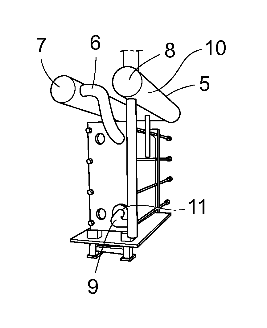
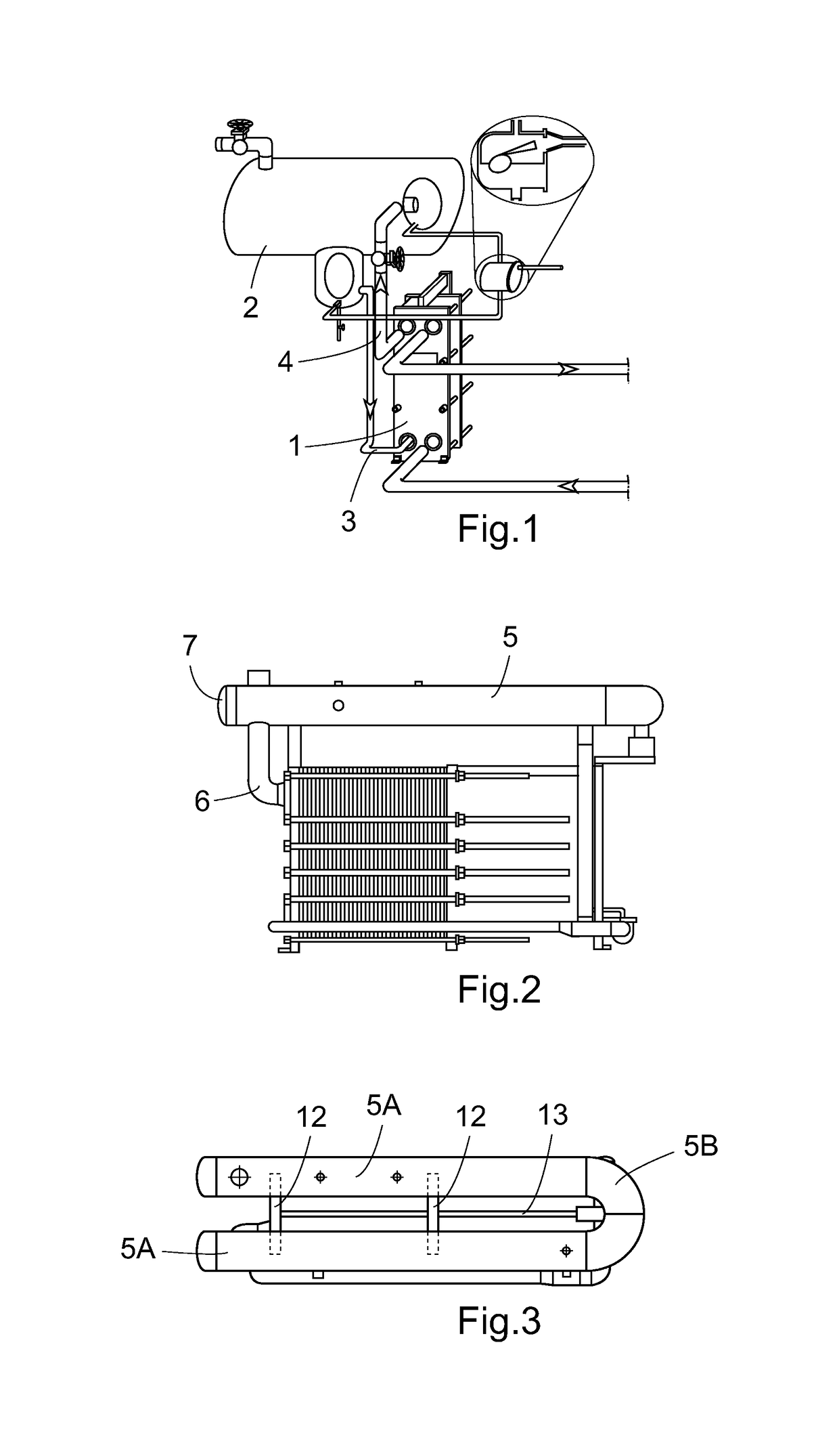
[0053]In FIG. 1 the general principle for a plate heat exchanger circulation evaporator system is shown. The evaporator 1 is connected to a vapour liquid separator 2 by two pipes 3, 4, a lower pipe leg 3 feeding the evaporator 1 and an upper pipe leg 4 which returns the partially evaporated liquid.

[0054]In case of an insoluble oil heavier than the refrigerant present in the refrigeration system, e.g. oil / ammonia, the oil is drained from the separator bottom and is collected in a vessel (not shown) at the lowest part of the refrigeration system and may be drained from there. The primary duty of the oil in the system is to lubricate moving parts of the compressors and to seal in order to prevent refrigerant from leaking. It is important that oil is prevented from reaching the evaporator and the oil is therefore collected before entering the evaporator and returned to the compressor.

[0055]The separator 2 always maintains a liquid level usually well above the top of the evaporator. The ...


PUM


Abstract

Liquid separator (2), designed as a U-shaped pipe (5) and arranged essentially horizontally, for a plate heat exchanger evaporator (1) system for separation of liquid droplets from vapor transported from the evaporator to the separator.

Description

[0001]This application is a US national phase application under 35 U.S.C. § 371 of International Application serial number PCT / SE2008 / 051257, filed Nov. 4, 2008, and claims the benefit of a foreign priority application filed in Sweden, serial number 0702440-9, filed Nov. 5, 2007, and also claims the benefit under 35 U.S.C. § 119(e) of U.S. provisional application Ser. No. 60 / 988,136, filed Nov. 15, 2007.FIELD OF THE INVENTION[0002]The present invention relates to a liquid separator to be used with a refrigeration evaporator system.BACKGROUND[0003]In refrigeration evaporator systems the refrigerant leaves a condenser as a slightly sub-cooled liquid at a high temperature and pressure. Before the refrigerant enters the evaporator the pressure of the refrigerant has to be brought down to the evaporating pressure and temperature by expanding the refrigerant. In this process a part of the refrigerant vaporises. The energy released by the cooling / expansion is absorbed by the evaporating re...

Claims


Application Information

Patent Timeline
Patent Type & Authority Patents(United States)
IPC IPC(8): F28F3/04F25B39/02F25B43/00F28D9/00
CPCF25B43/00F28D9/00F25B2400/23F25B2341/0011F25B39/022
Inventor SOLLIE, BJORNSTROMBLAD, MATSSTENHEDE, CLAES
Owner ALFA LAVAL CORP AB
Why Eureka
Try Eureka