
Lift truck with mast

a technology of lift trucks and masts, applied in the direction of lifting devices, etc., can solve the problem of limiting and achieve the effect of maximizing the operator's field of view

Inactive Publication Date: 2018-07-17
RAYMOND LTD
View PDF3 Cites 0 Cited by
  • Summary
  • Abstract
  • Description
  • Claims
  • Application Information

AI Technical Summary

Benefits of technology

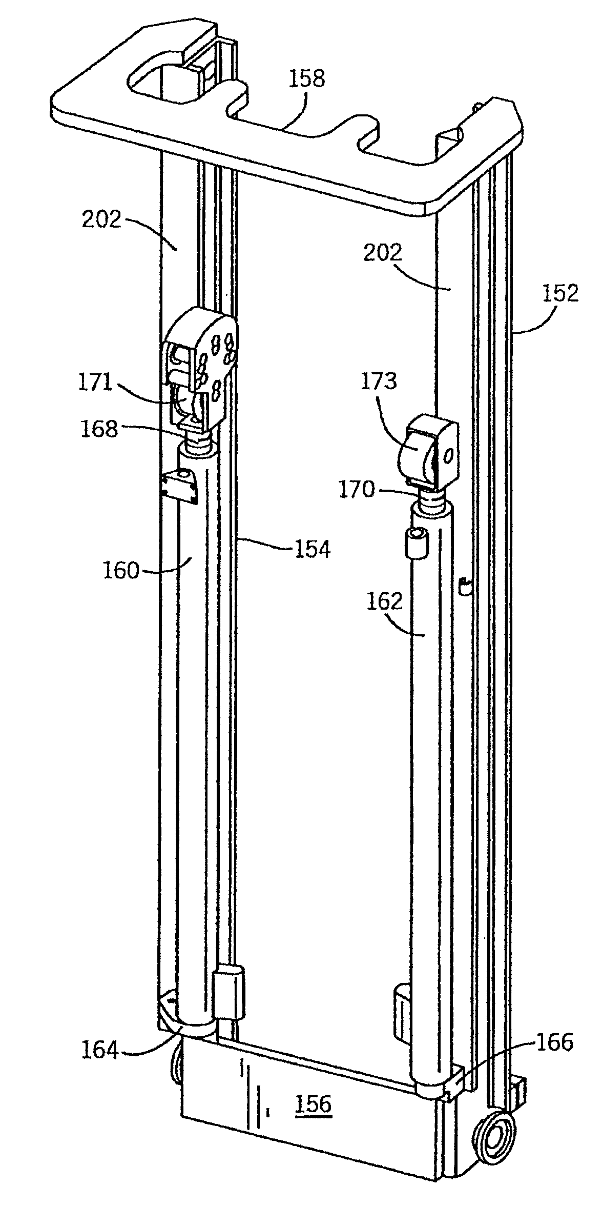
[0010]The present invention is a lift truck in which the mast elements and associated lift elements are arranged to maximize the operator's field of view when looking forward from the operator compartment. In a preferred embodiment, the lift truck includes an operator compartment and a pair of forks extending away from said operator compartment in a forward direction. A pair of mast columns are interposed between the operator compartment and the forks. Components mounted on at least one of the mast columns are arranged to fall within a viewing shadow so as not to obstruct the operator's field of view.

Problems solved by technology

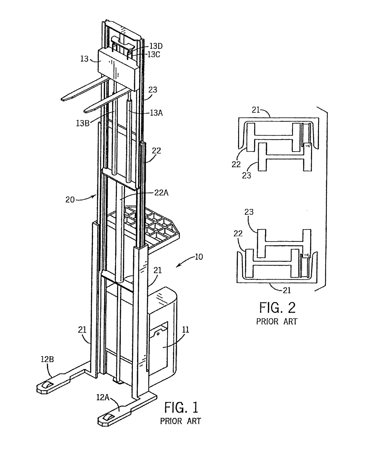
These mast elements plus the associated hydraulic hoses and electrical cable provide obstructions which limit the operator's field of view when looking forward towards the forks from the operator compartment 10.
A significant constraint on the design of a lift truck mast structure is its fore to aft dimension.

Method used


Image

  • Lift truck with mast
  • Lift truck with mast
  • Lift truck with mast

Examples


Embodiment Construction

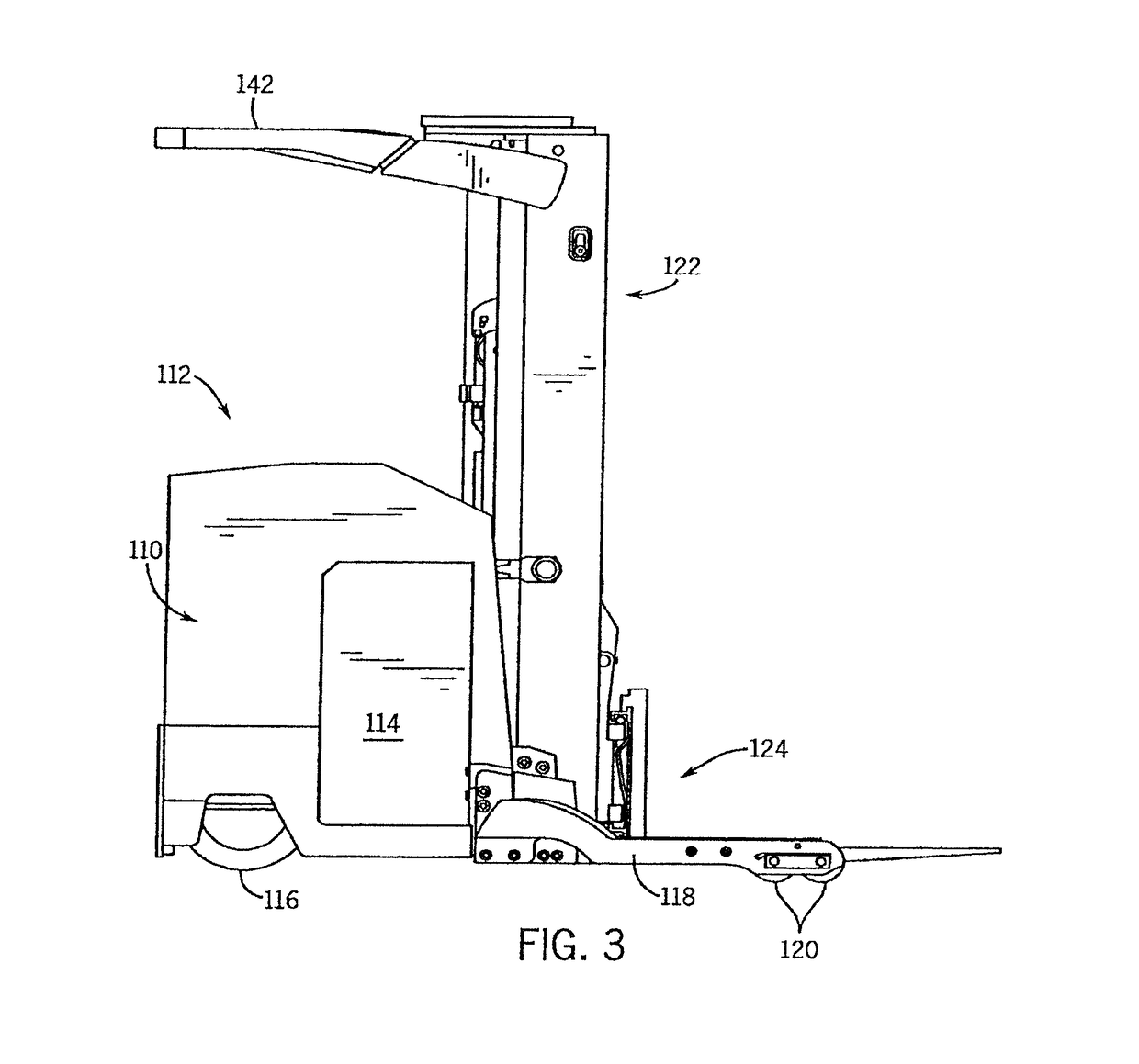
[0020]Referring particularly to FIG. 3, a lift truck which employs a preferred embodiment of the invention includes a power unit 110 having an operator's compartment 112 located to the rear and a battery compartment 114 located at the forward end. The battery supplies power to a traction motor drive (not shown) which rotates a steerable drive wheel 116 to propel and steer the lift truck. A pair of laterally spaced baselegs 118 indirectly connect to, and extend forward from the power unit 110, and each baseleg includes wheels 120 which support the truck.

[0021]A mast 122 connects to the front end of the power unit 110 and extends vertically upward therefrom. The mast 122 supports a fork carriage 124 which can be elevated to different heights as will be described in detail below. The mast 122 is comprised of three telescopic sections which are shown best in FIGS. 4A and 4B. These include a base section 126, an outer telescopic section 128, and an inner telescopic section 130. Rollers m...


PUM


Abstract

A lift truck includes an operator compartment and a pair of forks extending away from said operator compartment in a forward direction. A pair of mast columns are interposed between the operator compartment and the forks. Components mounted on at least one of the mast columns are arranged to fall within a viewing shadow so as not to obstruct the operator's field of view.

Description

CROSS-REFERENCE TO RELATED APPLICATIONS[0001]This is a continuation of U.S. patent application Ser. No. 12 / 941,647, filed Nov. 8, 2010, which is a continuation of U.S. patent application Ser. No. 12 / 106,802, filed Apr. 21, 2008, now U.S. Pat. No. 7,984,793, which is a continuation of U.S. patent application Ser. No. 11 / 467,754, filed Aug. 28, 2006, now U.S. Pat. No. 7,398,859, which is a continuation of U.S. patent application Ser. No. 10 / 634,377 filed Aug. 5, 2003, now U.S. Pat. No. 7,096,999, all of which are fully incorporated herein by reference.STATEMENT REGARDING FEDERALLY SPONSORED RESEARCH OR DEVELOPMENT[0002]Not applicable.FIELD OF INVENTION[0003]The field of the invention is industrial lift trucks, and particularly lift trucks with telescopic masts.BACKGROUND OF THE INVENTION[0004]A lift truck typically is a battery powered vehicle having an operator compartment with controls that enable the operator to drive the truck and to hoist materials and carry them quickly througho...

Claims


Application Information

Patent Timeline
Patent Type & Authority Patents(United States)
IPC IPC(8): B66F9/22B66F9/07B66F9/08
CPCB66F9/08B66F9/22B66F9/07
Inventor LEWIS, ROBERTWEST, JOHN A.
Owner RAYMOND LTD
Learn More