
Plug-in bulb coupling structure

a plug-in bulb and coupling structure technology, applied in the direction of coupling device connection, lighting support device, lighting and heating apparatus, etc., can solve the problems of low reliability, complex assembly and production, low production efficiency, etc., and achieve the effect of improving assembly strength, convenient and quick operation, and simplifying the assembly process

Inactive Publication Date: 2018-07-10
ZHUHAI HUIERYI ELECTRONICS CO LTD
View PDF9 Cites 0 Cited by
  • Summary
  • Abstract
  • Description
  • Claims
  • Application Information

AI Technical Summary

Benefits of technology

[0004]In order to solve the aforementioned problems in the prior art, the present invention provides a plug-in bulb coupling structure, by which, the drive circuit board and the SR of the power line can be assembled and connected to each other quickly; the operation is easy, convenient and quick and does not require any tools; the assembly process is significantly simplified and the assembly strength is enhanced, and the assembly efficiency is very high; furthermore, automated production can be realized.
[0014]With the technical solution of the present invention, the drive circuit board of the bulb and the SR of the power line may be assembled and connected to each other quickly, and functions of permanent connection, electricity conduction, tensile resistance and waterproof performance may be realized at the same time; furthermore, the operation is easy, convenient and quick, the assembly process is significantly simplified and the assembly strength is enhanced, and the assembly efficiency is very high; furthermore, automated mass production may be realized due to the simple structure and low difficulty in production and machining.
[0015]Additionally, the annular sealing skirt seals a plug-in joint between the plug-in lamp cap and the plug-in lamp holder effectively, thus to achieve the waterproof and dustproof purposes. Since it is not required to additionally provide other parts such as a waterproof ring, the assembly is easier and the assembly efficiency is higher; and it is safer to use, and the performance is stable and reliable.

Problems solved by technology

At present, a drive circuit inside a lamp cap of an existing commercially available LED string lamp product is generally directly connected to a power line by welding, resulting in complex assembly and production, low reliability and low production efficiency.
Furthermore, the waterproof performance may be realized by additionally providing components such as a waterproof ring; and the reliability of products is not high due to a large number of parts.

Method used


Image

  • Plug-in bulb coupling structure
  • Plug-in bulb coupling structure
  • Plug-in bulb coupling structure

Examples


Embodiment Construction

[0019]In order to make the objective, technical solution and advantages of the present invention clearer, the present invention will be further described below in detail with reference to the accompanying drawings by an embodiment. It should be understood that the specific embodiment to be described herein is merely used to explain the present invention, and the present invention is not limited thereto.

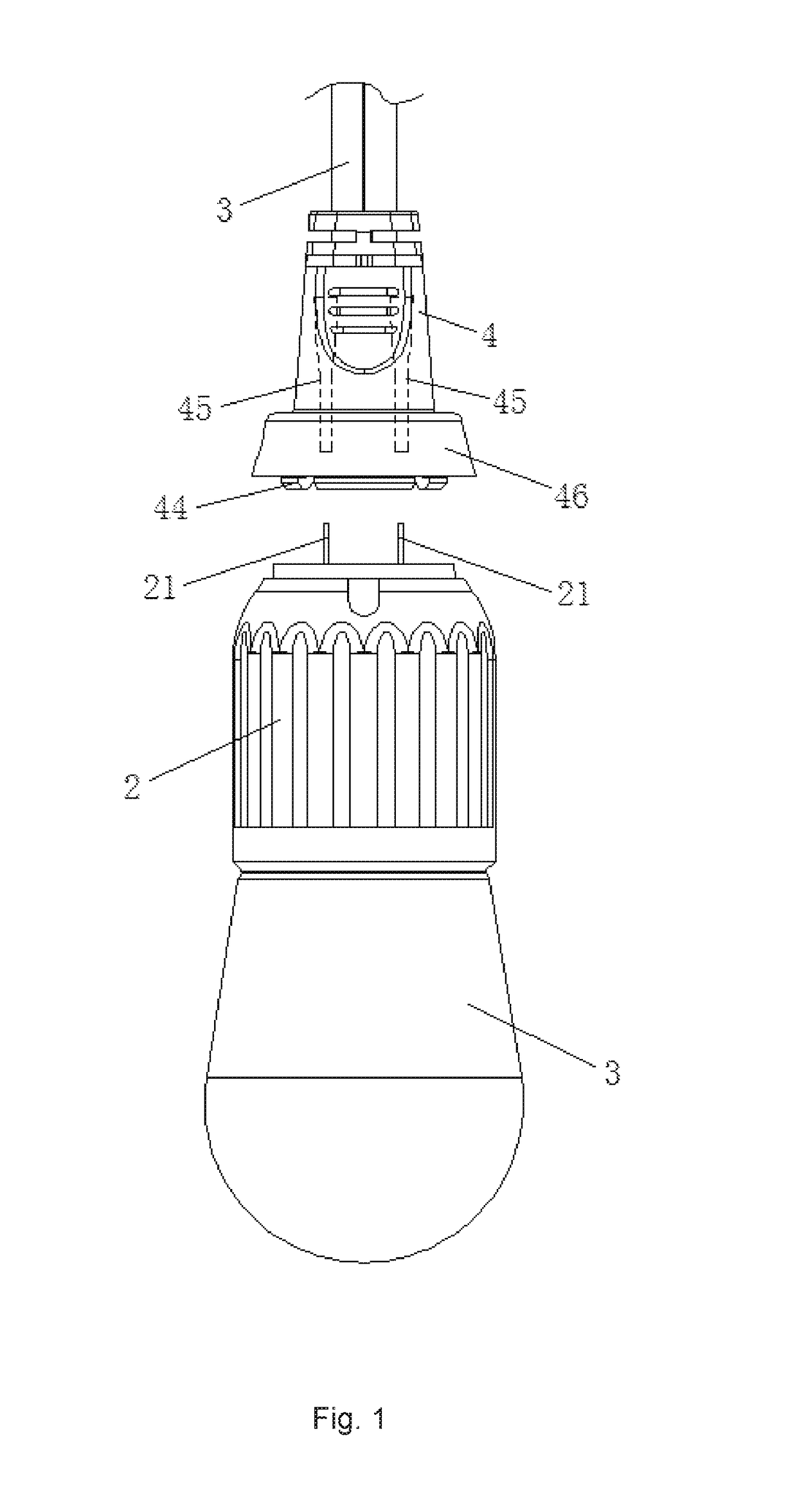
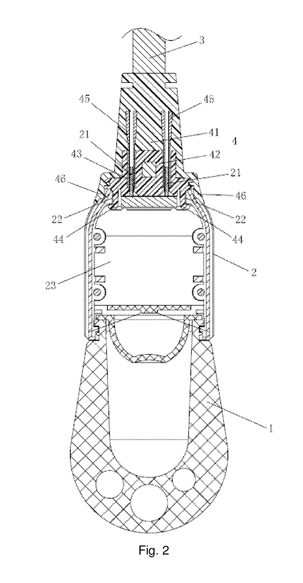
[0020]As shown in FIG. 1 to FIG. 2:

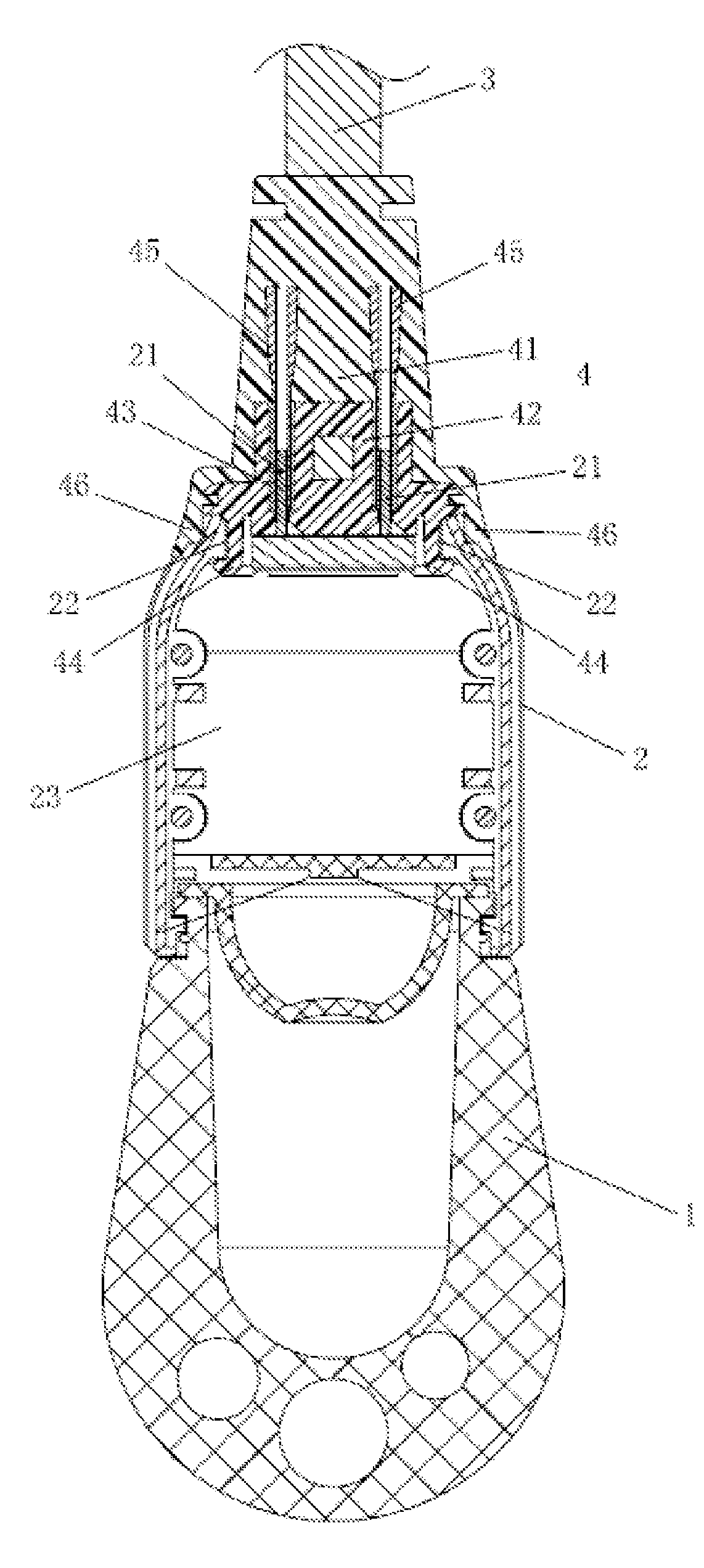
[0021]a plug-in bulb coupling structure to be described in the embodiment of the present invention includes a lamp cap 2 provided on a bulb 1 and a plug-in lamp holder 4 provided on a power line 3. A plug-in end of the plug-in lamp holder 4 is provided with plug-in holes 43 and raised barbs 44, conductive tubes 45 connected to a lead are provided in the plug-in holes 43, and the conductive tubes 45 may be a conductive copper tube; and correspondingly, the plug-in end of the plug-in lamp cap 2 is provided with conductive bars 21 and barb slots 22, and...


PUM


Abstract

The present invention relates to a plug-in bulb coupling structure, comprising a lamp cap provided on a bulb and a plug-in lamp holder provided on a power line, wherein a plug-in end of the plug-in lamp holder is provided with plug-in holes and raised barbs, and conductive tubes connected to a lead are provided in the plug-in holes; the plug-in end of the plug-in lamp cap is provided with conductive bars and barb holes, and the conductive bars are connected to a drive circuit board in the plug-in lamp cap. With the coupling structure of the present invention, the drive circuit board and the SR of the power line can be assembled and connected to each other quickly. The operation is easy, convenient and quick and does not require any tools.

Description

CROSS-REFERENCE TO RELATED APPLICATIONS[0001]The present application claims the benefit of Chinese Patent Application No. 201510890833.4 filed on Dec. 4, 2015, the contents of which are hereby incorporated by reference.TECHNICAL FIELD[0002]The present invention relates to the technical field of lighting lamps, and in particular to a plug-in bulb coupling structure.BACKGROUND OF THE PRESENT INVENTION[0003]At present, a drive circuit inside a lamp cap of an existing commercially available LED string lamp product is generally directly connected to a power line by welding, resulting in complex assembly and production, low reliability and low production efficiency. Furthermore, the waterproof performance may be realized by additionally providing components such as a waterproof ring; and the reliability of products is not high due to a large number of parts.SUMMARY OF THE PRESENT INVENTION[0004]In order to solve the aforementioned problems in the prior art, the present invention provides ...

Claims


Application Information

Patent Timeline
Patent Type & Authority Patents(United States)
IPC IPC(8): H01R33/06F21V31/00F21V21/002F21V23/06F21V15/01F21V23/00H01R33/97H01R13/58F21S4/10
CPCF21V23/06F21V15/01F21V21/002F21V23/001F21V31/005F21V23/003H01R33/97F21S4/10H01R13/5845H01R33/06
Inventor CHEN, JIANSHENGWANG, PINGFANG, JUN
Owner ZHUHAI HUIERYI ELECTRONICS CO LTD
Learn More