Handle device and breath analysis device

a technology of breath analysis and handle, which is applied in the direction of diagnostic recording/measuring, instruments, applications, etc., can solve the problems of inability to stably conduct breath to the measurement component, tube damage by the handle component, and inability to accurately measure the breath, etc., to achieve convenient use, reduce the effect of tube bending, and facilitate the measuremen

Active Publication Date: 2018-07-10
AEROCRINE AB +1
View PDF18 Cites 1 Cited by
  • Summary
  • Abstract
  • Description
  • Claims
  • Application Information

AI Technical Summary

Benefits of technology

[0009]The handle component of the present invention is given elasticity because the handle component has an inhalation hole near the tube. As a result, even if a certain amount of force is applied to the area around where the inhalation hole is formed, this elasticity will suppress bending of the tube, allowing measurement to be carried out more smoothly. Therefore, the device is easier to use and more convenient in breath measurement.

Problems solved by technology

Also, a tube for conducting breath to the measurement component is connected to the handle component which the user grasps for measurement, but if the user should bend the tube during use, the tube can be damaged by the handle component.
Nevertheless, if a force that exceeds the folded-back part is applied, there is the possibility that the tube will be bent, etc., by the folded-back part, which is formed from a hard material.
As a result, breath cannot be stably conducted to the measurement component, which means that the measurement must be performed again, etc., and this makes the device less convenient to use.

Method used


Image

  • Handle device and breath analysis device
  • Handle device and breath analysis device
  • Handle device and breath analysis device

Examples


Embodiment Construction

[0020]A handle device which uses in a breath analysis device of the present invention will be described.

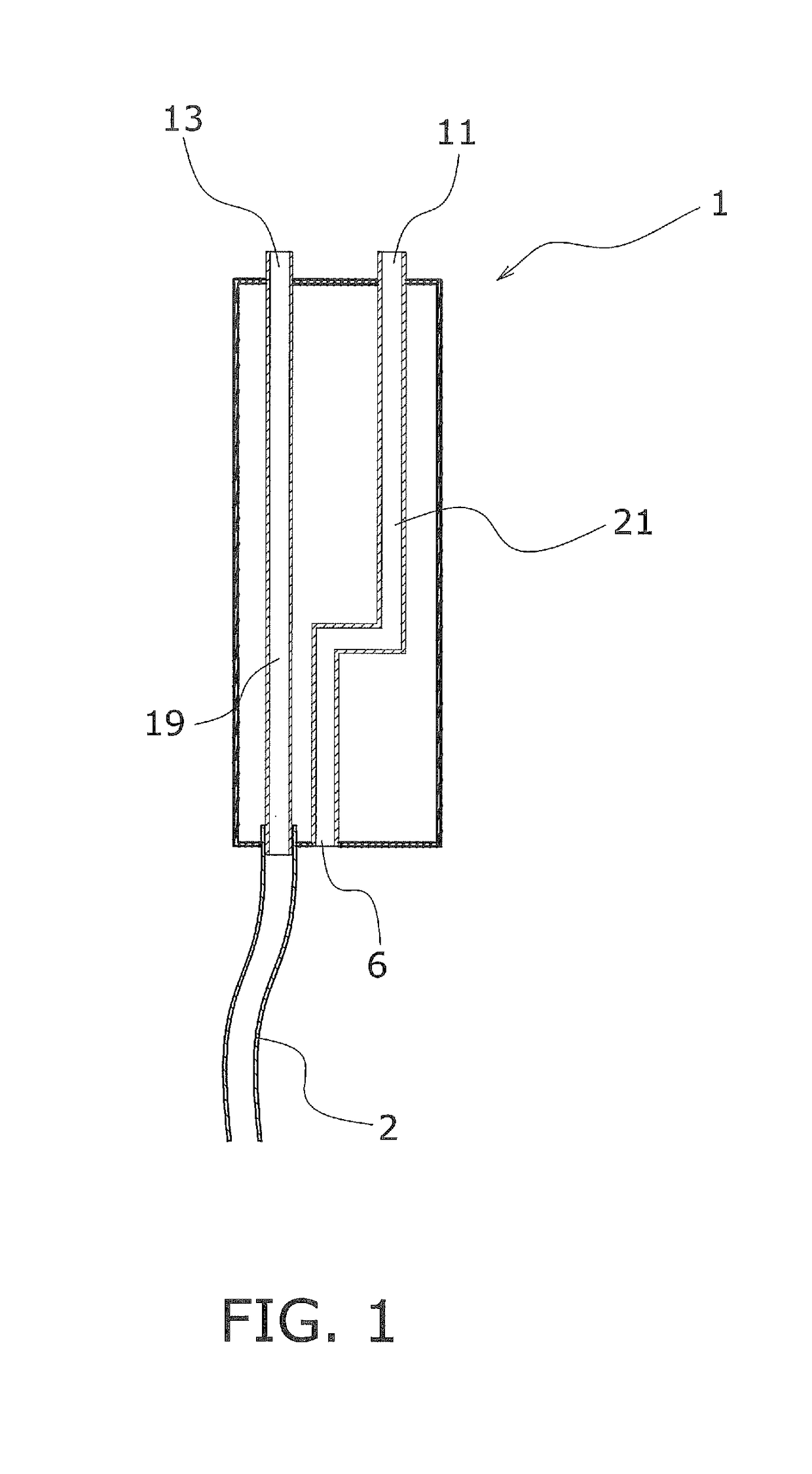
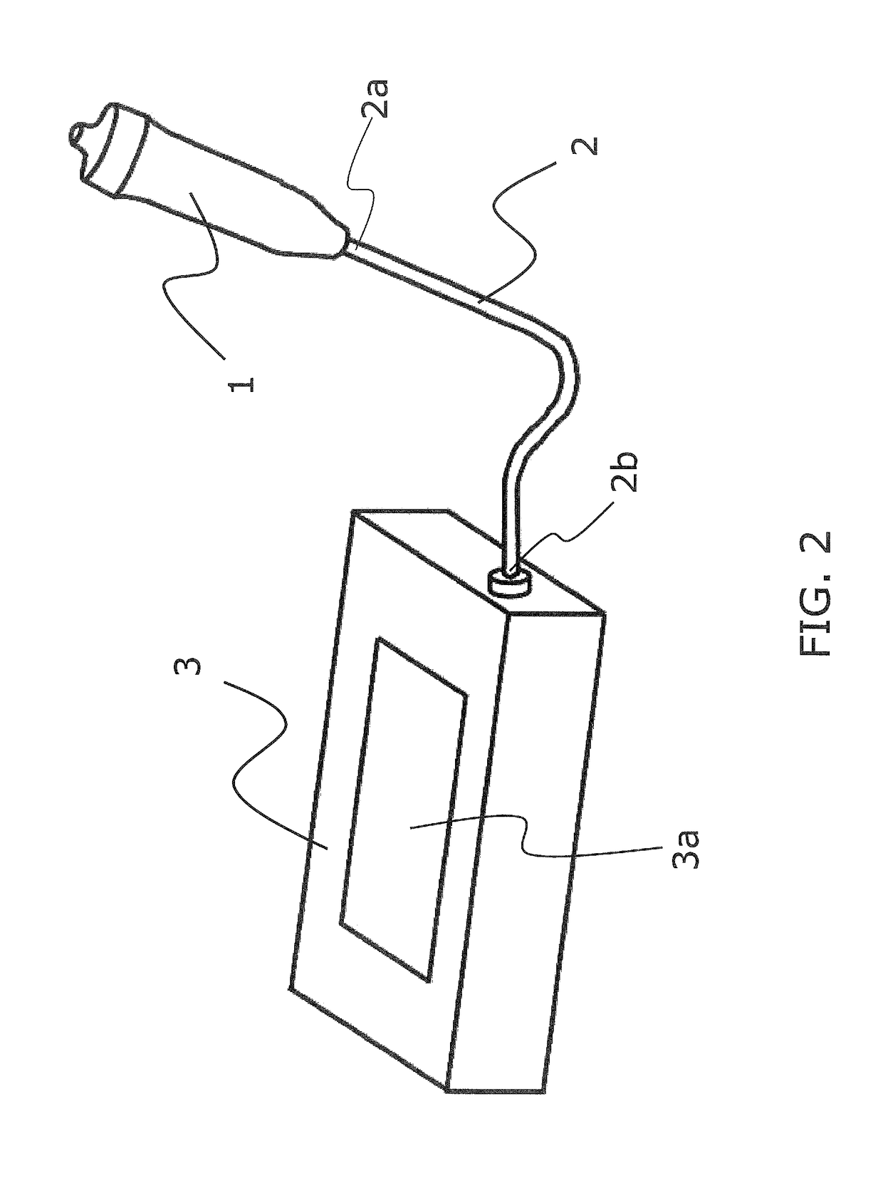
[0021]The breath analysis device of the present invention is a device for analysis of components in exhaled breath. The handle device of the present invention into which atmospheric air is inhaled and breath is exhaled in the analysis of breath comprises an inhalation hole, an inhalation inlet, an inhalation path, a breath discharge component, and an exhalation path. The inhalation hole is disposed near a tube connected for conducting exhaled breath to an analysis device main body for analyzing this breath, and is a hole through which atmospheric air is inhaled into the interior of the handle device. The inhalation inlet is a place through which atmospheric air inhaled from the inhalation hole is sent into the body. The inhalation path is disposed between the inhalation inlet and the inhalation hole. The breath discharge component takes in breath discharged from the body. The exha...


PUM

PropertyMeasurementUnit
thicknessaaaaaaaaaa
total surface areaaaaaaaaaaa
forceaaaaaaaaaa

Abstract

A handle component of the present invention into which atmospheric air is inhaled and breath is exhaled in the analysis of breath comprises inhalation holes, an inhalation inlet, an inhalation path, a breath discharge component, and an exhalation path. The inhalation holes are disposed near the tube connected for conducting exhaled breath to an analysis device main body for analyzing this breath, and are holes through which atmospheric air is inhaled into the interior of the handle component. The inhalation inlet is a place where the atmospheric air inhaled from the inhalation holes is sent into the body. The inhalation path is disposed between the inhalation inlet and the inhalation holes. The breath discharge component is a place where breath discharged from the body is taken in. The exhalation path is disposed between the breath discharge component and the tube.

Description

PRIORITY[0001]This application claims priority to International Application PCT / JP2013 / 002756, with an international filing date of Apr. 23, 2013 which claims priority to Japanese Patent Application No. JP 2012-098942 filed on Apr. 24, 2012. The entire disclosures of International Application PCT / JP2013 / 002756 and Japanese Patent Application No. JP 2012-098942 are hereby incorporated herein by reference.TECHNICAL FIELD[0002]The present invention relates to a breath analysis device and a handle device used in performing asthma analysis, pulmonary function analysis, and so forth.BACKGROUND ART[0003]In the past, the handle component and the measurement component in this type of breath analysis device were generally integrated, but there is a trend toward separating the handle component and the measurement component, and connecting the two by a tube, to make the product easier for the user to use, to improve the visibility of the measurement results, and so on.[0004]Also, a tube for con...

Claims


Application Information

Patent Timeline
Patent Type & Authority Patents(United States)
IPC IPC(8): A61B5/08A61B5/097G01N33/497G01N1/22
CPCA61B5/097A61B5/082G01N33/497G01N2001/2285G01N2001/2244G01N2001/2276
Inventor YANO, MASAYOSHIKIMURA, TAKASHISTARCK-JOHNSON, PETER HANS
Owner AEROCRINE AB
Why Eureka
Try Eureka