
Vertical thrust lever

a technology of vertical thrust and lever, which is applied in the direction of actuating personally, vertical landing/taking off aircraft, transportation and packaging, etc., can solve the problem that helicopters tend to be inefficient when flying forward

Active Publication Date: 2018-07-03
WISK AERO LLC
View PDF26 Cites 11 Cited by
  • Summary
  • Abstract
  • Description
  • Claims
  • Application Information

AI Technical Summary

Problems solved by technology

However, helicopters tend to be inefficient when flying forwards at a constant altitude.
As a result, it would be desirable for new controlle

Method used


Image

  • Vertical thrust lever
  • Vertical thrust lever
  • Vertical thrust lever

Examples


Embodiment Construction

[0009]The invention can be implemented in numerous ways, including as a process; an apparatus; a system; a composition of matter; a computer program product embodied on a computer readable storage medium; and / or a processor, such as a processor configured to execute instructions stored on and / or provided by a memory coupled to the processor. In this specification, these implementations, or any other form that the invention may take, may be referred to as techniques. In general, the order of the steps of disclosed processes may be altered within the scope of the invention. Unless stated otherwise, a component such as a processor or a memory described as being configured to perform a task may be implemented as a general component that is temporarily configured to perform the task at a given time or a specific component that is manufactured to perform the task. As used herein, the term ‘processor’ refers to one or more devices, circuits, and / or processing cores configured to process da...


PUM


Abstract

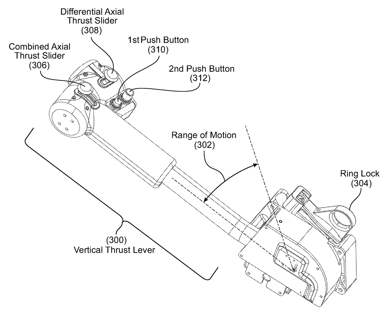
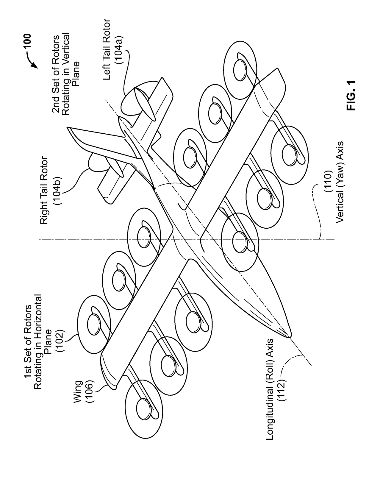
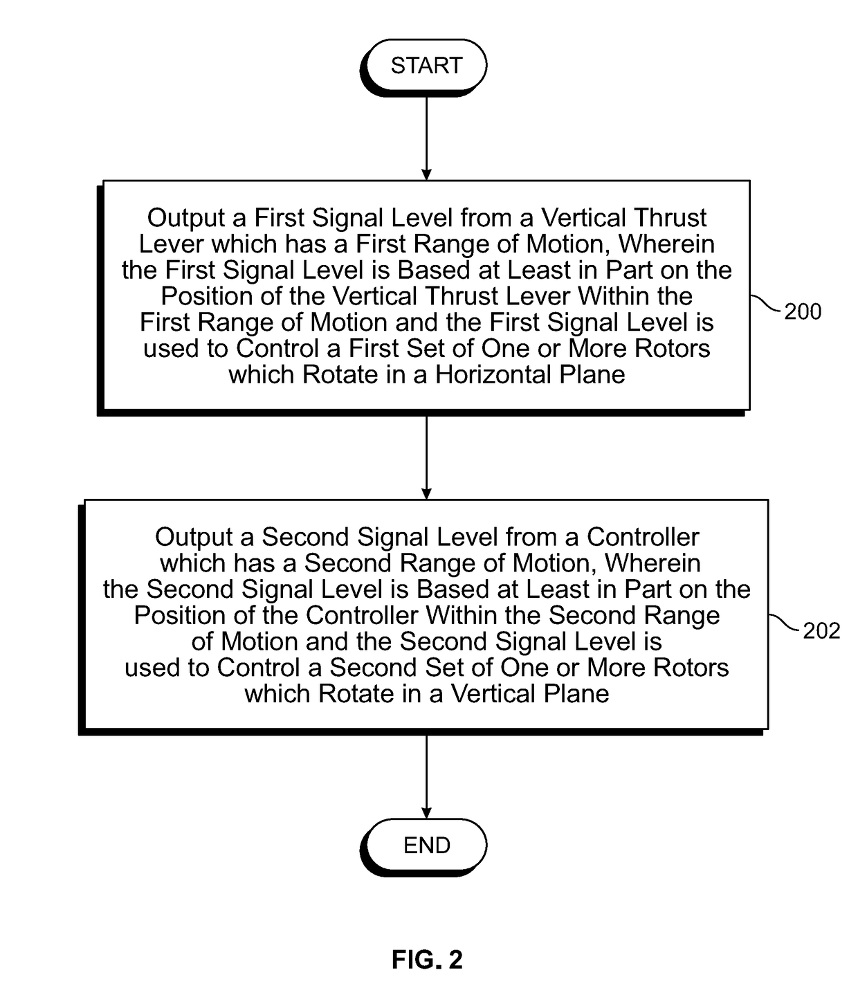
A vertical thrust lever has a first range of motion and is configured to output a first signal level where the first signal level is based at least in part on the position of the vertical thrust lever and the first signal level is used to control a first set of rotors which rotate in a horizontal plane. A controller has a second range of motion and is configured to output a second signal level where the second signal level is based at least in part on the position of the controller and the second signal level is used to control a second set of rotors which rotate in a vertical plane.

Description

BACKGROUND OF THE INVENTION[0001]Traditional types of aircraft tend to be optimized for either forward (e.g., horizontal) flight or vertical flight, but not both. For example, helicopters tend to be efficient and / or good at flying vertically. They can hover at a constant altitude and can also ascend or descend substantially vertically in a relatively efficient manner (e.g., as measured by power consumption). However, helicopters tend to be inefficient when flying forwards at a constant altitude. In contrast, airplanes (with aerodynamic lift forces acting on the wings of the airplanes) tend to be good at forward flight, but cannot hover or ascend / descend substantially vertically. New types of aircraft are being developed which are good at both forward flight and vertical flight. As a result, it would be desirable for new controllers for piloting these new types of aircraft to be developed because existing controllers may not be optimized for this new manner of flying.BRIEF DESCRIPTIO...

Claims


Application Information

Patent Timeline
IPC IPC(8): B64C13/14B64C29/00
CPCB64C13/14B64C29/0025B64C27/56B64D31/04B64C13/0421
Inventor WONG, SHELDONSHOEMAKER, WILLIAM C.
Owner WISK AERO LLC
Learn More