Optical and mechanical assembly for wall wash lighting

a technology of optical and mechanical assembly and wall wash, which is applied in the direction of semiconductor devices for light sources, fixed installations, lighting and heating apparatus, etc., can solve the problems of poor uniformity, inability to provide for high-ceiling illumination, and poor uniformity, so as to reduce glare

Active Publication Date: 2018-06-26
ABL IP HLDG
View PDF17 Cites 4 Cited by
  • Summary
  • Abstract
  • Description
  • Claims
  • Application Information

AI Technical Summary

Benefits of technology

[0005]To address these and other shortcomings, an improved wall wash lighting assembly is provided for a recessed light fixture, which is mountable in a ceiling. The wall wash lighting assembly can include an optical assembly and a trim face plate mechanically connected thereto. The optical assembly has a first kicker reflector, a second kicker reflector and a light-shaping optical film. The first kicker reflector reflects light from a light source, such as an LED light source. The second kicker reflector reflects light received from the first kicker reflector toward an adjacent wall. The light-shaping optical film spreads any light received from the light source and the first and second kicker reflectors in a uniform light pattern onto a target area, such as onto the adjacent wall or in a downward direction parallel to the adjacent wall. The trim face plate has a trim opening through which light is outputted onto the target area. The trim face plate can be an angle-cut trim face plate. The combination of these components allows for the design of a wall wash lighting assembly that is compact and can distribute light evenly onto an adjacent wall for any trim aperture size.
[0006]The first and second kicker reflectors can have different types of reflective surfaces. For example, the first kicker reflector can have a reflective metallized finish, and the second kicker reflector can have a reflective white finish. The reflective white finish of the second kicker reflector can diffuse, as well as reflect, the received light to help smooth the light pattern on the adjacent wall.
[0007]Furthermore, the wall wash lighting assembly can utilize detachable fasteners to allow for the interchangeability of components in the lighting assembly. For example, the optical assembly can be detachably connected to the trim face plate, e.g. at bosses on the trim face plate, using fasteners such as a screw(s). In this way, different types of interchangeable trim face plates can be used in combination with the optical assembly. The trim face plates can have different aesthetic features (e.g., square or round) or different optical features (e.g., an angle-cut trim to reduce glare, or a non-angle-cut trim). The same fasteners can also be used to connect mounting springs to the bosses on the trim face plate. The mounting springs are used to mount the optical assembly and trim face plate into a housing or mounting frame of the recessed light fixture.
[0008]Similarly, the optical film can also be detachably connected to at least one of the kicker reflectors of the optical assembly or the trim face plate, using detachable fasteners such as a screw(s). In this way, different types of interchangeable optical films, such as those with different light patterns, can be used in the wall wash lighting assembly to provide for a desired uniform light pattern on the adjacent wall or in a direction parallel to the adjacent wall. For example, it is possible to configure a different light beam distribution horizontally on the wall, by simply replacing the optical film, e.g., switching a 90×1 degree film to a 60×1 degree film. The wall wash lighting assembly can provide a wider uniform light beam distribution with a 90×1 degree film, or a narrower uniform light beam distribution with a 60×1 degree film.

Problems solved by technology

The first approach has the benefits of a suitably high-ceiling illumination but suffers from uniformity distribution on the adjacent wall.
For example, as shown in FIG. 6, the light distributed on an adjacent wall has a large gradient of light to dark resulting in poor uniformity.
The second approach is, however, unable to provide for a high-ceiling illumination, as shown in FIG. 7.

Method used


Image

  • Optical and mechanical assembly for wall wash lighting
  • Optical and mechanical assembly for wall wash lighting
  • Optical and mechanical assembly for wall wash lighting

Examples


Embodiment Construction

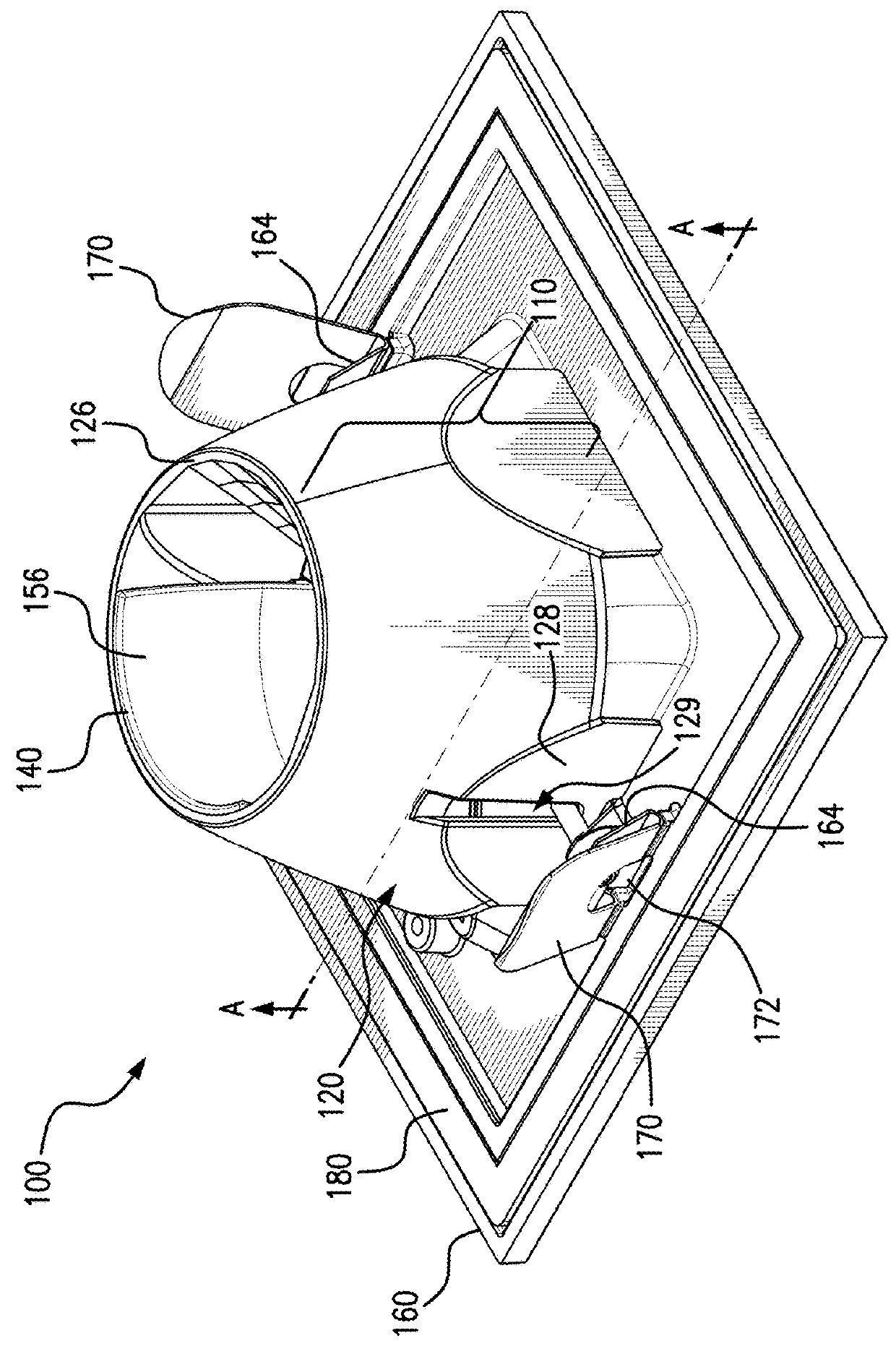
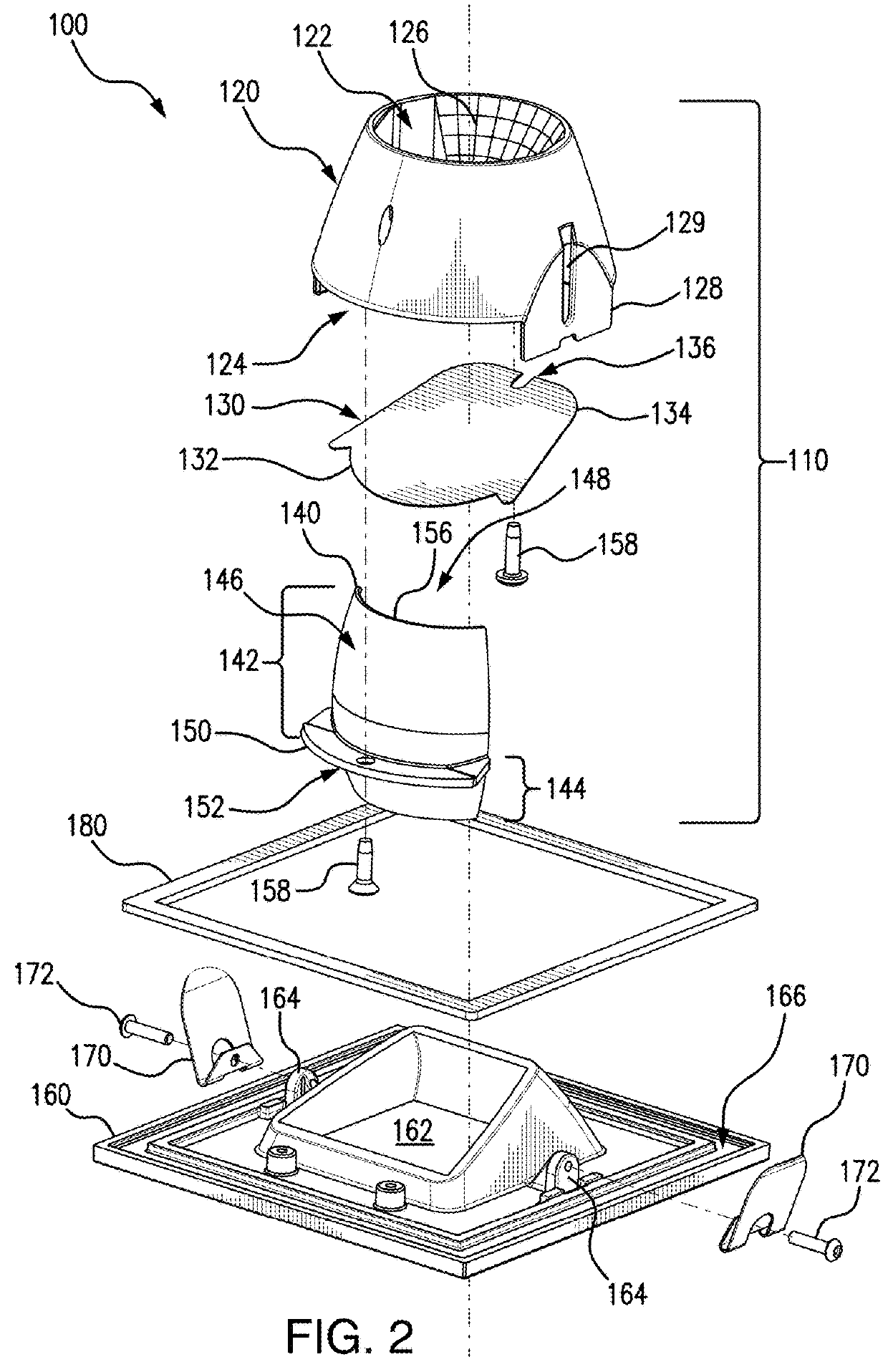
[0017]FIG. 1 illustrates a wall wash lighting assembly 100 for a recessed light fixture, which is mountable in a ceiling. The wall wash lighting assembly 100 includes an optical assembly 110 and a trim face plate 160. The optical assembly 110 includes a first kicker reflector 120, an optical film 130 (not shown), and a second kicker reflector 140. The optical assembly 110 is detachably connected to the trim face plate 160 and mounting springs 170 using detachable fasteners 172, such as screws. The mounting springs 170 are used to mount the wall wash lighting assembly 100 into the ceiling, such as onto a housing or mounting frame of a recessed light fixture. The wall wash lighting assembly 100 can also include a gasket 180 to reduce or prevent light leakage between the trim face plate 160 and a room side of the ceiling, when the wall wash lighting assembly 100 is mounted in the ceiling. The various components of the wall wash lighting assembly 100 are shown in greater detail in the e...


PUM


Abstract

A wall wash lighting assembly is provided for a recessed light fixture mountable on a ceiling. The lighting assembly includes an optical assembly and a trim face plate connected thereto. The optical assembly has a first kicker reflector, a second kicker reflector and a light-shaping optical film. The first kicker reflector reflects light from a light source. The second kicker reflector reflects light received from the first kicker reflector toward an adjacent wall. The light-shaping optical film spreads light from the light source and the first and second kicker reflectors in a uniform light pattern in a target area, such as onto the adjacent wall or downward in a direction parallel to the adjacent wall. The trim face plate has a trim opening through which light is outputted onto the target area. The lighting assembly can employ detachable fasteners to allow for the interchangeability of the optical film and the trim face plate.

Description

RELATED CASES[0001]The present application claims priority under 35 U.S.C. § 119(e) based on U.S. Provisional Application Ser. No. 61 / 945,365 filed on Feb. 27, 2014, which is incorporated by reference herein in its entirety.FIELD[0002]The present disclosure is related to a recessed light fixture, and more particularly, to a wall wash lighting assembly for a recessed light fixture.BACKGROUND[0003]A downlight wall wash is a type of recessed light fixture, which is mounted in a ceiling. The wall wash is used to distribute light onto a wall that is adjacent to the light fixture. Lighting designers use various criteria to evaluate the quality of such a light fixture, such as how well the fixture can distribute light on the adjacent wall. Ideally, lighting designers would like to have the light distributed evenly on the wall with the light directed very close to the ceiling and a smooth transition down the wall toward the floor. Multiple wall washers, which are arranged next to each other...

Claims


Application Information

Patent Timeline
Patent Type & Authority Patents(United States)
IPC IPC(8): F21V7/00F21S8/02F21V5/04F21V13/04F21Y115/10
CPCF21V7/0033F21S8/026F21Y2115/10F21V13/04F21V5/046
Inventor ZHANG, CHIFRYZEK, AARON P.
Owner ABL IP HLDG
Why Eureka
Try Eureka