Apparatus for retrieving units from a storage system

a technology for storage systems and apparatuses, applied in the direction of gearing, de-stacking articles, electric motor propulsion transmission, etc., to achieve the effect of improving efficiency, balancing system cost and energy consumption, and gaining efficiency

Active Publication Date: 2018-06-19
OCADO INNOVATION
View PDF16 Cites 23 Cited by
  • Summary
  • Abstract
  • Description
  • Claims
  • Application Information

AI Technical Summary

Benefits of technology

[0030]By arranging the bulky components of the load handling device above the container-receiving space, the footprint of the load handling device is reduced compared to the cantilever designs shown in FIGS. 3(a) to 3(c) and described in NO317366, in which the bulky components are housed in a vehicle module disposed to one side of the container-receiving space. Advantageously, the load handling device of the invention occupies the space above only one stack of containers in the frame, in contrast to the cantilever design shown in FIGS. 3(a) to 3(c) which occupies the space above two stacks. This means that, by virtue of the invention, the efficiency of operation of the storage system can be improved, because the reduced footprint allows more load handling devices to be accommodated and reduces the likelihood of one device obstructing the optimum path of another.
[0033]Alternatively, the wheels may include integrated motors, for example motors integrated within the wheel hubs. In this way, each wheel is a self-container drive unit, and drive belts are not required. This arrangement is advantageous as it reduces the size of the load-handling device and facilitates servicing.
[0042]The lower part may comprise a frame structure for supporting the wheels of the wheel assembly. The frame structure may be arranged around the container-receiving space. For example, the container-receiving space may be bounded on four sides by the frame structure. One or more elements of the frame structure may be moveable to raise and lower a first set of the wheels with respect to a second set of the wheels, thereby to facilitate engagement of either the first set of wheels or the second set of wheels with a first or a second set of rails or tracks, respectively. The moveable elements of the frame structure may be driven by a motor housed in the upper part of the load handling device.
[0047]In this aspect, the provision of a first handling device capable of lifting a plurality of containers from a stack in a single operation along with a second handling device capable of lifting a single container and moving the container laterally provides an optimum solution when seeking to retrieve a container which is located in the middle or bottom of a stack. In such a case, only two lifting operations need be carried out to retrieve the target container, which greatly increases the speed and efficiency of the retrieval process compared to prior art arrangements in which only one container can be lifted at a time.
[0049]In a typical application, multiple handling devices may be employed so that multiple containers can be lifted and moved simultaneously. The handling devices may be of different types, and may be selected to balance the cost and energy consumption of the system with the speed and flexibility of operation. One benefit of the present invention is that, because the load handling devices occupy the space above only one stack, the efficiency of a multiple-device system can be improved compared to prior art load handling device designs which occupy two or more stack spaces. The gain in efficiency may arise from being able to accommodate more load handling devices in a given system, from optimising the routing of the device using the space gained by the reduced device footprints, or from a combination of these factors.

Problems solved by technology

Advantageously, each load handling device occupies substantially only a single grid space in the storage system.

Method used


Image

  • Apparatus for retrieving units from a storage system
  • Apparatus for retrieving units from a storage system
  • Apparatus for retrieving units from a storage system

Examples


Embodiment Construction

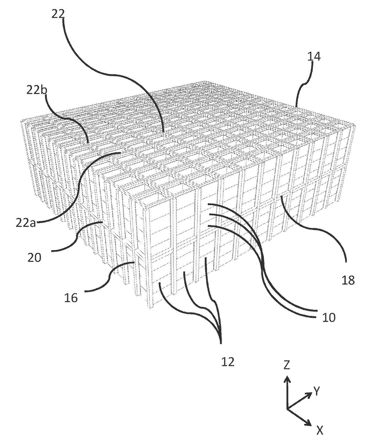
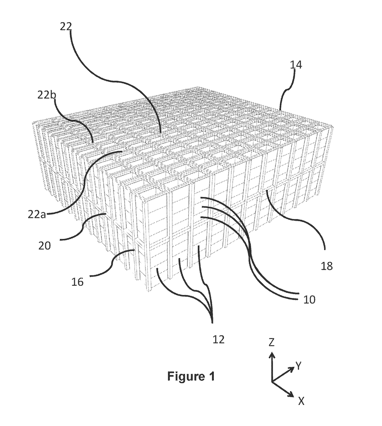
[0066]FIG. 5 shows a load handling device 100 according to an embodiment of the invention. The load handling device 100 comprises a vehicle 102 equipped with a winch or crane mechanism 104 to lift a storage container or bin 106, also known as a tote, from above. The crane mechanism 104 includes winch cables 108 and a grabber plate 110. The grabber plate 110 is configured to grip the top of the container 106 to lift it from a stack of containers 106 in a storage system of the type shown in FIGS. 1 and 2.

[0067]Referring also to FIGS. 6(a) and 6(b), the vehicle 102 comprises an upper part 112 and a lower part 114.

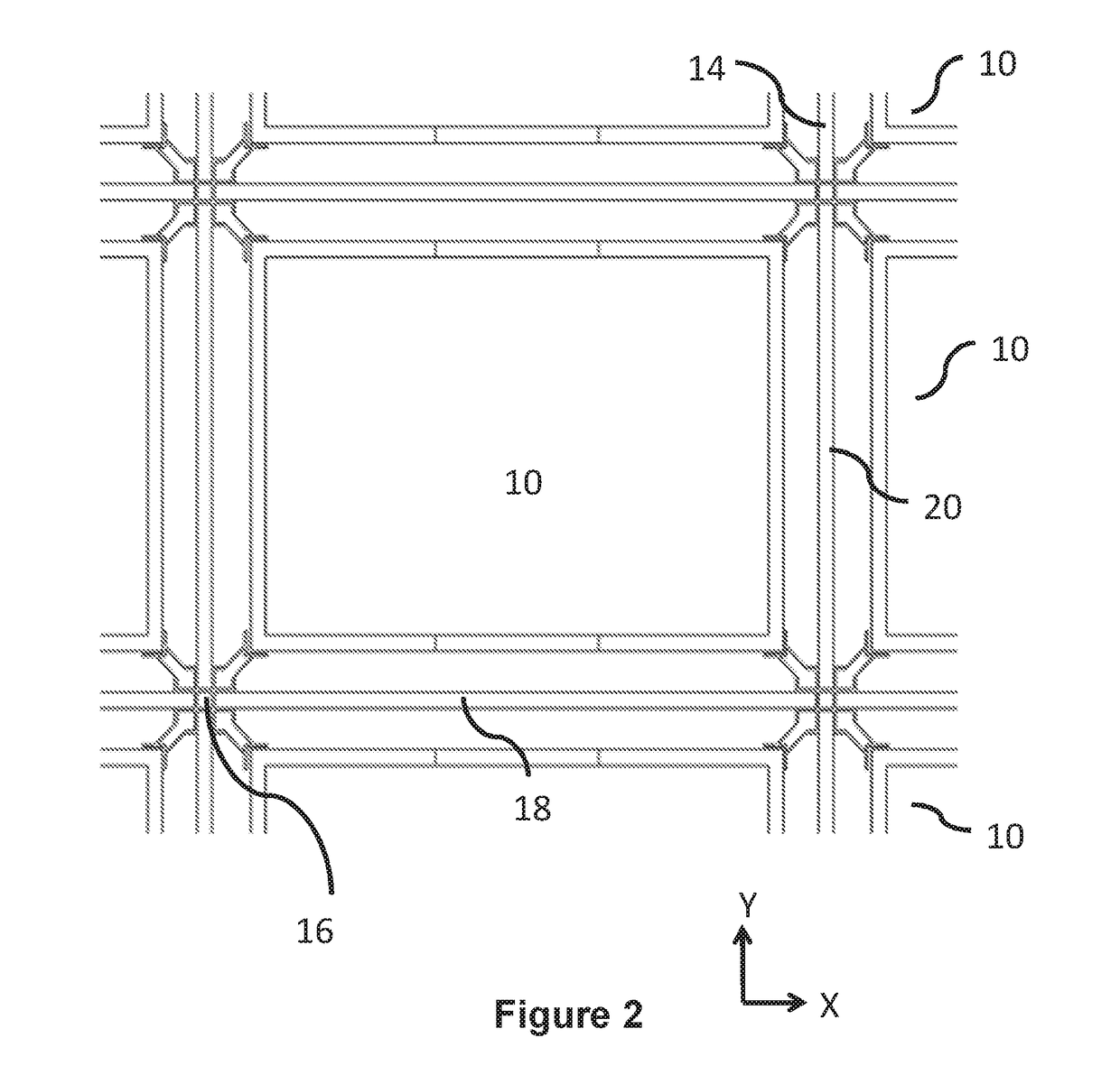
[0068]The lower part 114 is fitted with two sets of wheels 116, 118, which run on rails provided at the top of the frame of the storage system. At least one wheel of each set 116, 118 is driven to enable movement of the vehicle 102 in X- and Y-directions respectively along the rails. As will be explained below, one or both sets of wheels 116, 118 can be moved vertically to lif...


PUM


Abstract

A storage system and a load handling device for lifting and moving containers stacked in the storage system are described. The storage system includes a plurality of rails or tracks arranged in a grid pattern above the stacks of containers. The grid pattern can include a plurality of grid spaces and each stack is located within a footprint of only a single grid space. The load handling device is configured to move laterally on the rails or tracks above the stacks. The load-handling device includes a container-receiving space located above the rails or tracks in use and a lifting device arranged to lift a container from a stack into the container-receiving space. The load handling device has a footprint that, in use, occupies only a single grid space in the storage system.

Description

FIELD OF THE INVENTION[0001]The present invention relates to apparatus for retrieving units form a storage system. In particular, but not exclusively, the invention relates to robotic devices for handling storage containers or bins in a store comprising a grid of stacked units.BACKGROUND TO THE INVENTION[0002]Some commercial and industrial activities require systems that enable the storage and retrieval of a large number of different products. One known system for the storage and retrieval of items in multiple product lines involves arranging storage bins or containers on rows of shelves arranged in aisles. Each bin or container holds a plurality of products of one product type. The aisles provide access between the rows of shelves, so that the required products can be retrieved by operatives or robots that circulate in the aisles. It will be appreciated, however, that the need to provide aisle space to access the products means that the storage density of such systems is relatively...

Claims


Application Information

Patent Timeline
Patent Type & Authority Patents(United States)
IPC IPC(8): B65G59/02B65G1/04B65G57/03
CPCB65G1/0464B65G1/0492B65G57/03B65G59/02B65G1/04G06Q50/28G06Q10/087B65G1/0414B65G1/0457B65G1/065B65G1/0478B65G2201/0235
Inventor LINDBO, LARS SVERKER TURESTADIE, ROBERT ROLFWHELAN, MATTHEW ROBERTBRETT, CHRISTOPHER RICHARD JAMES
Owner OCADO INNOVATION
Why Eureka
Try Eureka