
Integrated navigation method based on star sensor calibration

A star sensor and integrated navigation technology, applied in integrated navigators, satellite radio beacon positioning systems, navigation, etc., can solve the problems of discontinuous navigation information, easy to be interfered, unstable integrated filters, etc., and achieve integrated navigation Excellent system accuracy, high navigation accuracy, and the effect of suppressing error accumulation

Inactive Publication Date: 2007-07-11
BEIHANG UNIV
View PDF0 Cites 18 Cited by
  • Summary
  • Abstract
  • Description
  • Claims
  • Application Information

AI Technical Summary

Problems solved by technology

But its disadvantage is that it cannot provide high-precision attitude information, the navigation information is discontinuous, and it is easy to be interfered.
Usually the integrated navigation system adopts a simple combination method, using the error equation of the inertial navigation system as the state equation of the integrated navigation system, taking the position, velocity and attitude information output by satellite navigation and celestial navigation as observations, and using Kalman filter to combine Navigation information processing corrects inertial navigation errors. The biggest advantage of this combination method is that it is easy to implement and improves the navigation accuracy of the system. However, the accuracy of integrated navigation depends on the accuracy of observations. The accuracy of position and speed is equivalent to that of GPS, and the accuracy of attitude is comparable to The attitude accuracy determined by the star sensor is equivalent, but the optimal combination of each navigation system cannot be achieved, and the accuracy of the integrated navigation system is better than that of any single navigation system, and the error accumulation caused by the model over time and some system errors Any sudden change will cause error transmission, which often leads to the instability of the combined filter. Therefore, the error of the auxiliary navigation system must be further compensated to obtain higher navigation accuracy.

Method used


Image

  • Integrated navigation method based on star sensor calibration
  • Integrated navigation method based on star sensor calibration
  • Integrated navigation method based on star sensor calibration

Examples


Embodiment Construction

[0013] The present invention will be described in further detail below in conjunction with the accompanying drawings.

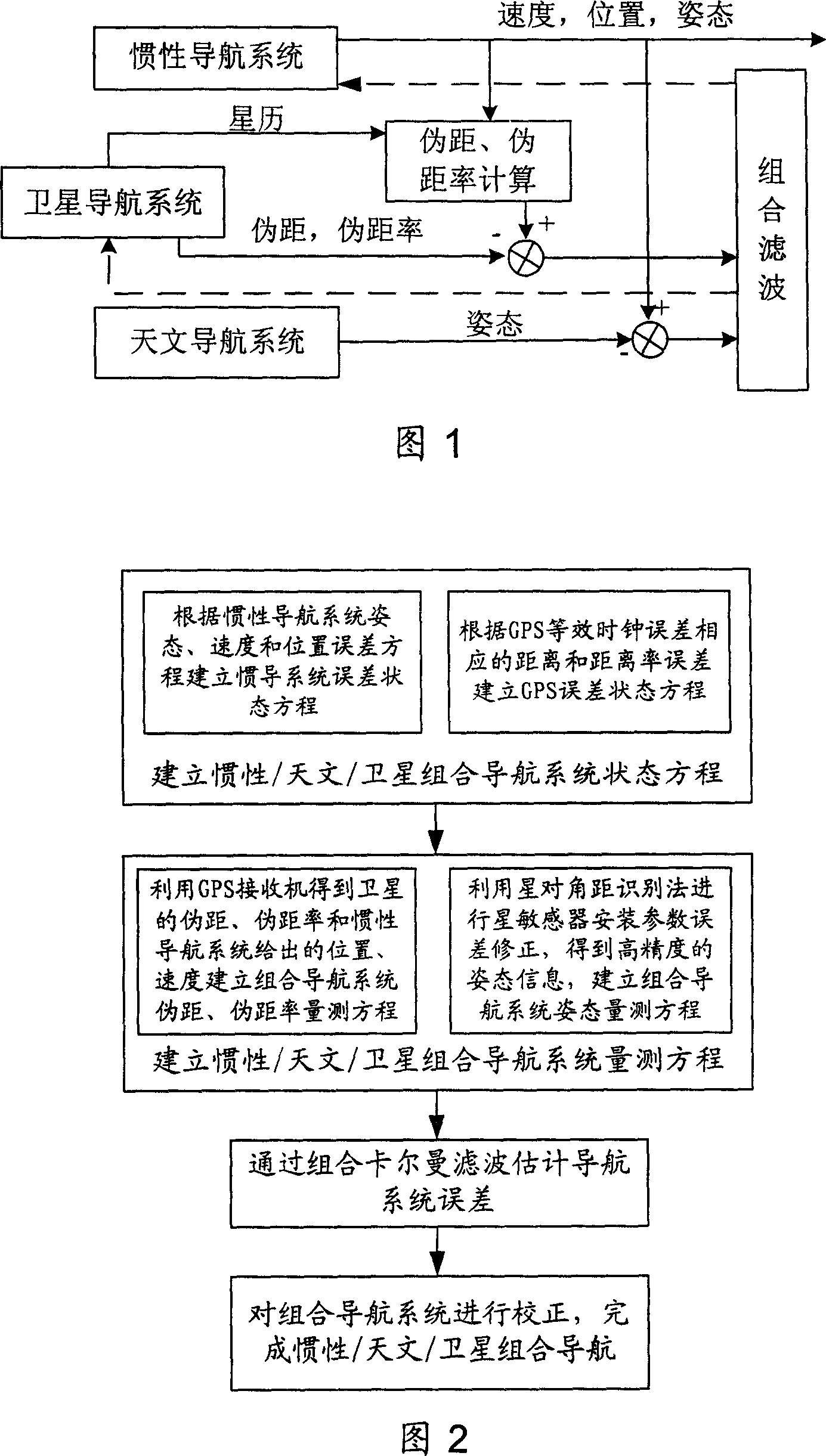
[0014] As shown in Figure 1, the inertial navigation system obtains the speed, position and attitude information of the carrier through strapdown calculation; the satellite navigation system uses the speed and position information calculated by the inertial navigation system and the ephemeris received by the GPS receiver to obtain the relative The inertial navigation system gives the pseudo-range and pseudo-range rate at the position, and calculates the difference between the pseudo-range and pseudo-range rate obtained by the receiver to obtain the pseudo-range and pseudo-range rate observation information; Sensor installation parameter error correction, and then the carrier attitude information is obtained through the star map recognition algorithm and attitude determination algorithm of celestial navigation, and the error amount of the inertial navigation sy...


PUM


Abstract

The combined navigation based on star sensor calibration optimizing the inertia, astronomical and satellite for all kinds of high precision fly guide. It modifies the installation error based on the star diagonal distance to get high precision information, calculating the disguise distance and disguise distance ratio relative to the inertia guide position through the astronomical data provided by GPS and the location and speed provided by the inertia guide and comparing with the disguise distance and its ratio measured by the GPS as the measuring value, through combined Kalman filter model to estimate the inertia guide system and GPS error and ratifying accordingly to these two systems based on feedbacks. It can improve combined guide navigation precision and reach a high quality combination, whose precision is better than any single guide navigation precision.

Description

technical field [0001] The invention relates to an inertial / astronomy / satellite combined navigation method, in particular to a deep integrated combined navigation method based on star sensor calibration, which can be used for various high-precision aircraft navigation. Background technique [0002] Existing various single navigation systems all have their advantages and disadvantages. The inertial navigation system is a completely autonomous positioning and navigation system. It can continuously provide position, speed and attitude information in real time. Its short-term accuracy is very high, but the error of the inertial system will continue to accumulate over time. Therefore, pure inertial guidance The system is difficult to meet the requirements of long-range high-precision navigation. The satellite navigation system can provide the three-dimensional position and speed information of the carrier in real time all-weather, and the error does not accumulate over time, and...

Claims


Application Information

Patent Timeline
Patent Type & Authority Applications(China)
IPC IPC(8): G01C21/00G01C21/24G01C21/20G01C21/02G01C21/16G01S1/02G01S5/02G01S5/14G01S19/38
Inventor 房建成徐帆全伟钟慧敏王科宫晓琳
Owner BEIHANG UNIV
Learn More