Deposit removing device
一种附着物、驱动装置的技术,应用在工件冷却装置、工件清洁装置、工件表面处理设备等方向,能够解决高效地除去、喷嘴接近板状部件的表面、板状部件损伤等问题
- Summary
- Abstract
- Description
- Claims
- Application Information
AI Technical Summary
Problems solved by technology
Method used
Image
Examples
example 1
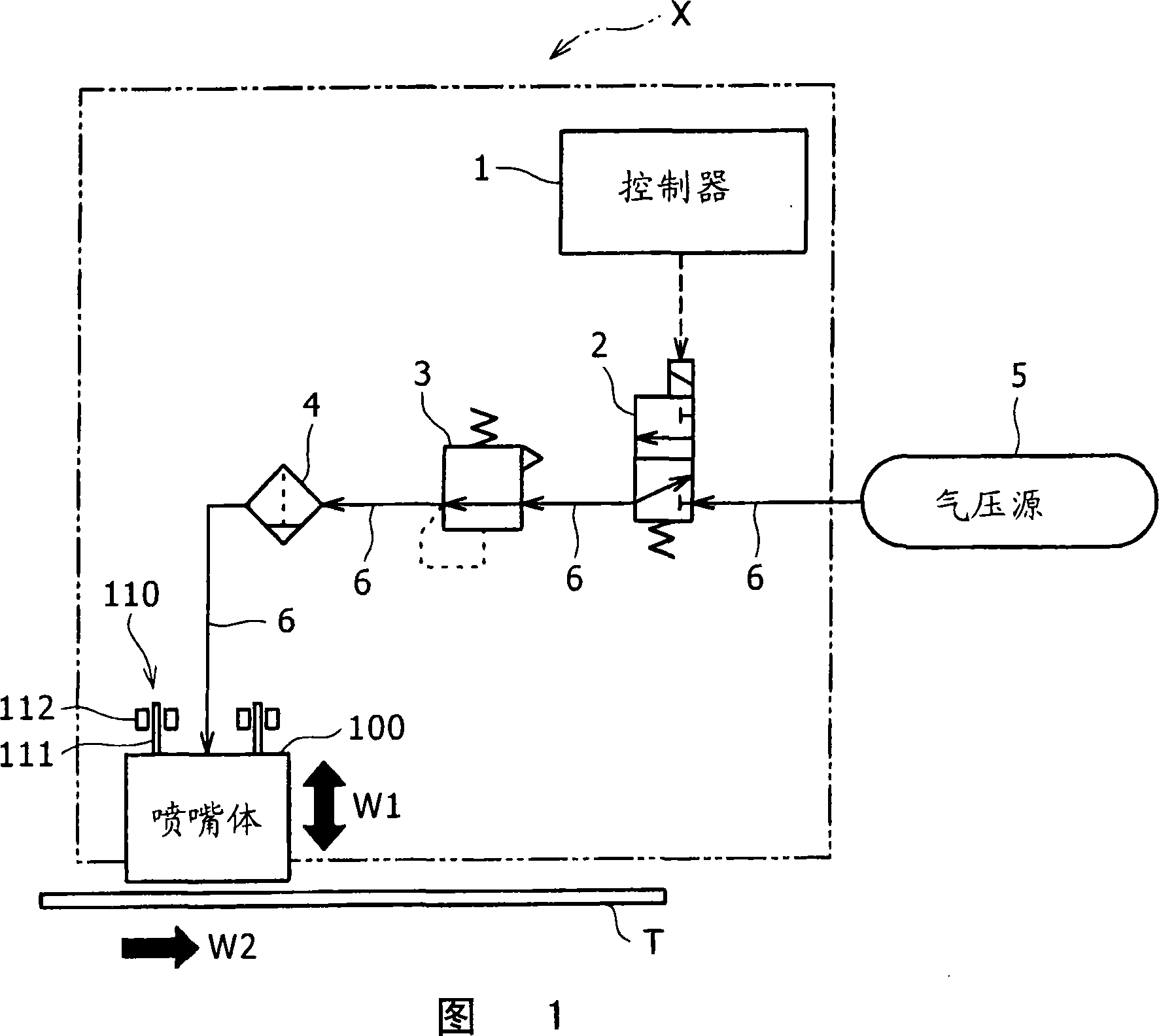
[0081] Next, an attached matter removing device X1 according to Example 1 of the present invention will be described with reference to FIGS. 11 and 12 . FIG. 11 is a schematic longitudinal cross-sectional view of the nozzle body 100a, and FIG. 12 is a perspective view of the nozzle body shown in FIG. 11 . Components that are the same as those in the above-described embodiment are denoted by the same reference numerals, and descriptions thereof are omitted.
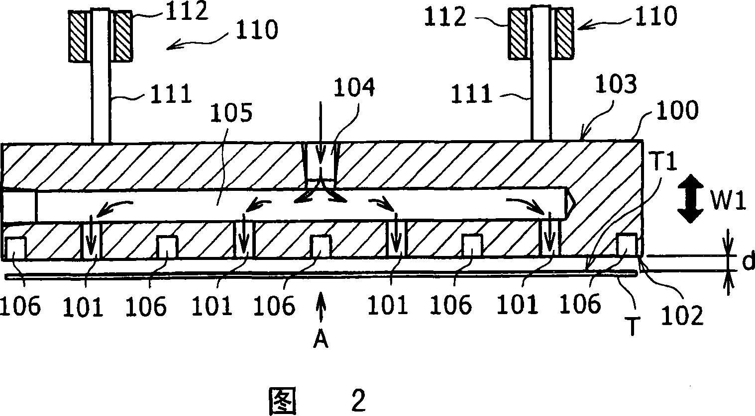
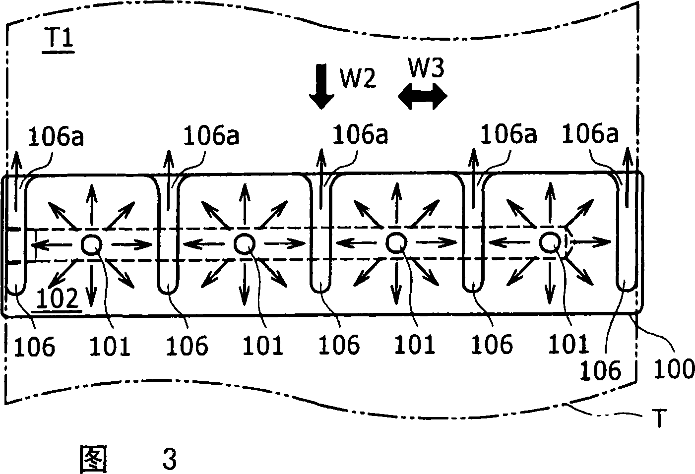
[0082] The deposit removing device X1 according to the present embodiment is included in the deposit removing device X of the above-mentioned embodiments because, as shown in FIG. 11 and particularly FIG. 12, the deposit removing device X1 uses a nozzle body 100a in which The opposite surface 102 to the top surface T1 has grooves 107 . In FIG. 11 , although the groove 106 (refer to FIGS. 2 to 4 ) formed in the nozzle body 100 is not shown, the nozzle body 100 a may include the groove 106 .
[0083] As shown in FIG. 11 , ...
example 2
[0085] Next, an attached matter removing device X2 according to Example 2 of the present invention will be described with reference to FIGS. 13 and 14 .
[0086] In this example, a nozzle body 100b shown in FIG. 13 is used. In the nozzle body 100b of the attachment removing device X2, on its opposite surface, four injection ports 101 are arranged at intervals along the direction W3 of the plate-shaped member T, which is the same as the direction W3 of the plate-shaped member T. The conveying direction W2 (refer to FIG. 13 ) is substantially perpendicular to the moving direction W1 (refer to FIG. 14 ) of the nozzle body 100b; On the downstream side in the direction W2, they are arranged at predetermined intervals in parallel with the ejection port series 101a. By juxtaposing the injection port series 101a and the injection port series 101b, even when deposits that cannot be removed by the spray port series 101a remain on the plate member T, the deposits are removed by the spra...
example 3
[0093] Next, Example 3 will be explained with reference to FIG. 15 (block diagram). The deposit removing device X3 according to this example is configured to include: an air release hole 109b provided in the nozzle body 100b (example 2, refer to FIG. 13 ); an oil separator 120 (an example of a deposit separating / recovering device), which The oil separator separates liquid or mist rolling oil (an example of liquid deposits) contained in the air discharged from 109b from the air, and recovers it to the oil tank 130 arranged outside the apparatus; and for The separated rolling oil is directed to the injector 122 of the oil tank 130 . Since other components of the attachment removing device X3 are similar to those of the attachment removing device X2, description thereof is omitted here.
[0094] The oil separator includes various possible types, but here is exemplified a device in which there is an oil filter 120a for separately separating the rolling oil from the air, and a dev...
PUM
 Abstract
Description
Claims
Application Information
 - Generate Ideas
- Intellectual Property
- Life Sciences
- Materials
- Tech Scout
- Unparalleled Data Quality
- Higher Quality Content
- 60% Fewer Hallucinations
Browse by: Latest US Patents, China's latest patents, Technical Efficacy Thesaurus, Application Domain, Technology Topic, Popular Technical Reports.
© 2025 PatSnap. All rights reserved.Legal|Privacy policy|Modern Slavery Act Transparency Statement|Sitemap|About US| Contact US: help@patsnap.com


