
Leaking current controller

A control device and leakage current technology, applied in circuit devices, emergency protection circuit devices, automatic disconnection emergency protection devices, etc., can solve the problems of complicated circuit structure of leakage current control devices and other problems

Inactive Publication Date: 2007-06-27
LG ELECTRONICS (TIANJIN) APPLIANCES CO LTD
View PDF0 Cites 5 Cited by
  • Summary
  • Abstract
  • Description
  • Claims
  • Application Information

AI Technical Summary

Problems solved by technology

[0008] However, in the leakage current control device of the above-mentioned prior art, due to the large number of windings wound in the above-mentioned zero-sequence current transformer (ZCT), resulting in The circuit structure of the leakage current control device is relatively complicated

Method used


Image

  • Leaking current controller
  • Leaking current controller

Examples


Embodiment Construction

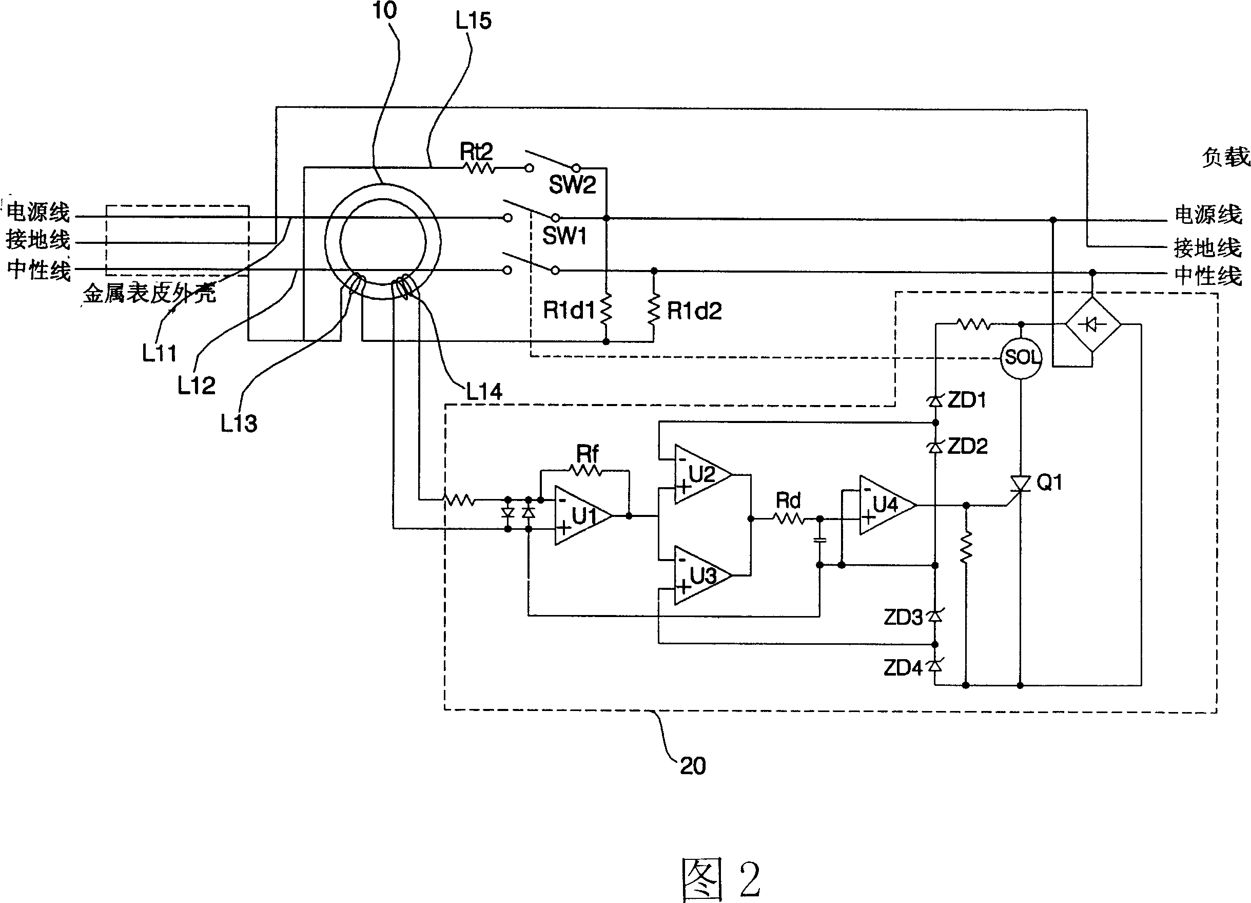
[0024] As shown in Figure 2, the leakage current control device includes: a power line (HOT, L11) that penetrates the zero sequence current transformer (ZCT, 10) and supplies power to the load (LOAD); Neutral wire (NEUTRAL, L12) of zero-sequence current transformer (ZCT, 10); ground wire (GROUND); the power wire (HOT, L11), neutral wire (NEUTRAL, L12), ground wire (GROUND) Metal skin (Sheath) shell; Test Line (L15) used to test the above zero sequence current transformer (ZCT, 10).

[0025] Wherein, the above-mentioned leakage current control device is provided in an air conditioner, and is used to detect the leakage and ground fault of the power supply to the load of the above-mentioned air conditioner.

[0026] The power cut-off unit 20 includes a plurality of amplifiers (OP-AMP), a plurality of diodes, and a plurality of resistors. Among them, the secondary coil (L14) of the zero sequence current transformer (ZCT, 10) is wound according to the above The magnetic flux of the zer...


PUM


Abstract

This invention relates to a control device for leak current including: a zero-order current mutual inductor, a primary coil, a secondary coil and a supply cut-off part, in which, the primary coil contains a supply line, a neutral line and a surface line, and the supply line passes through the zero-order current mutual-inductor and is connected with the first cut-off switch, the neutral line passes through the mutual-inductor and is connected with the second cut-off switch, one end of the surface line is contacted with the metal surface shell of the supply line and the neutral line, the other end winds the mutual-inductor and is connected with the supply line and the neutral line by resistors, a test line, one end of which contacts with the surface line and the other end is connected with a test switch by a resistor and connected with the supply line via the test switch, which can tests out leak current and earth fault current at the same time.

Description

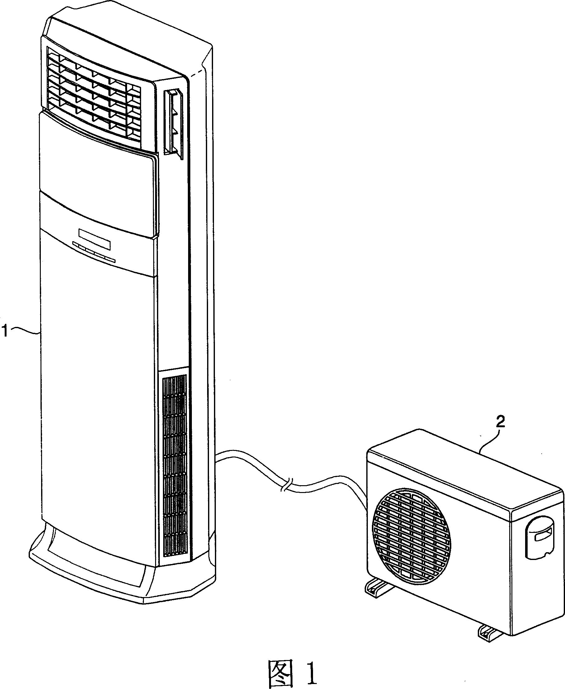
Technical field [0001] The invention relates to a leakage current control device. Background technique [0002] Generally speaking, an air conditioner is used to exhaust air in a cold / warm state into the room, while purifying the indoor air, and providing users with a comfortable indoor environment. [0003] As shown in Figure 1, the air conditioner is composed of an indoor unit 1 and an outdoor unit 2. During heating operation, a high-temperature and high-pressure refrigerant flows in the indoor heat exchanger, and the refrigerant is released to the air circulating in the indoor heat exchanger. Heat, and exhaust the warm air to the indoor side, thereby heating the room; during the cooling operation, low-temperature and high-pressure refrigerant flows in the indoor side heat exchanger, and the refrigerant absorbs the air contained in the air circulating in the indoor side heat exchanger. Heat, and discharge cold air to the indoor side, so as to cool the room. [0004] In the abov...

Claims


Application Information

Patent Timeline
IPC IPC(8): H02H3/32
Inventor 金一旭
Owner LG ELECTRONICS (TIANJIN) APPLIANCES CO LTD
Learn More