Method for winding coil of three-phase motor

A technology of three-phase motor and winding method, which is applied in the field of coil winding of three-phase motors, can solve problems such as difficulty in realizing low noise, large deviation of sine wave distribution, and unsatisfactory excitation distribution, and achieve simple manufacture, stable operation, Effect of reducing motor vibration

Active Publication Date: 2014-04-30
SUZHOU AICHI GAUSS MOTORS
View PDF5 Cites 4 Cited by
  • Summary
  • Abstract
  • Description
  • Claims
  • Application Information

AI Technical Summary

Problems solved by technology

However, the excitation distribution state synthesized by the excitation of each phase deviates greatly from the ideal sine wave distribution, so the excitation distribution in this state makes it difficult to achieve low vibration and low noise of the motor
That is to say, the simplistic winding structure will cause unsatisfactory excitation distribution

Method used


Image

  • Method for winding coil of three-phase motor
  • Method for winding coil of three-phase motor
  • Method for winding coil of three-phase motor

Examples


Embodiment 1

[0034] like image 3As shown, a coil winding method for a three-phase motor, the first phase coil group U is introduced from the first slot, drawn from the sixth slot to the thirteenth slot, and then introduced from the thirteenth slot, from the tenth The eighth wire slot is drawn to the twenty-fourth wire slot to form the winding U1, and then the reverse lead is introduced from the twenty-fourth wire slot, drawn from the nineteenth wire slot to the twelfth wire slot, and then introduced through the twelfth wire slot, from The seventh wire slot is connected to the neutral point of the Y-connection to form the winding U2;

[0035] The second phase coil group V is introduced from the fifth wire slot, drawn from the tenth wire slot to the seventeenth wire slot, and then introduced through the seventeenth wire slot, and drawn out from the twenty-second wire slot to the fourth wire slot to form winding V1 , and then the reverse lead is introduced from the fourth wire slot, drawn f...

Embodiment 2

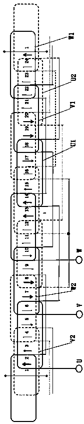
[0041] like Figure 4 As shown, a coil winding method for a three-phase motor, the first phase coil group U is introduced from the first slot, drawn from the seventh slot to the thirteenth slot, and then introduced from the thirteenth slot, from the tenth The nine wire slots are connected to the first wire slot to form the winding U1, which is introduced from the twenty-fourth wire slot, drawn from the sixth wire slot to the twelfth wire slot, and then introduced from the twelfth wire slot, and then from the eighteenth wire slot The central point connected to the Y-shaped connection and the twenty-fourth slot are drawn out respectively to form the winding U2, and the initial lead-in ends of the two windings are connected;

[0042] The second phase coil group V is introduced from the fifth wire slot, drawn from the eleventh wire slot to the seventeenth wire slot, then introduced from the seventeenth wire slot, drawn out from the twenty-third wire slot and connected to the fifth...


PUM


Abstract

The invention discloses a method for winding a coil of a three-phase motor. The three-phase motor comprises a stator, a rotor and coil sets, wherein the stator is provided with twenty four coil slots which are ranked clockwise or anticlockwise; the rotor is provided with a quadrupole composed of a permanent magnet; the coil sets comprise the first-phase coil set, the second-phase coil set and the third-phase coil set; the first-phase coil set, the second-phase coil set and the third-phase coil set are in Y-type connection and respectively comprise two windings wound around the coil slots; the multiple coil slots are formed between the first-phase coil set and the second-phase coil set and between the second-phase coil set and the third-phase coil set at intervals. By the adoption of the technical scheme, the method has the advantages that the number of the windings is reduced, the ideal sine wave distributed magnetic exciting coil can be generated, the vibration of the motor is reduced effectively, the noise of the motor is lowered effectively, the motor operates stably, and the motor is easy to manufacture at the same time.

Description

technical field [0001] The invention relates to a three-phase motor, in particular to a coil winding method of the three-phase motor. Background technique [0002] In the prior art, a general rotary three-phase motor energizes the wound stator to excite the corresponding rotor so that the rotor generates torque. In order to make the rotor rotate smoothly, the excitation distribution of the stator is adjusted sinusoidally. [0003] Ideally, a general three-phase motor is composed of 24 slots in the stator and a 4-pole brushless DC motor composed of permanent magnets in the rotor. For a long time, the distribution of such slots has been used as a representative coil, and the concentric winding One phase pole pair uses two windings, which are used as the slot reference to make the electrical angle 120 degrees apart in the circumferential direction. The U-phase coil spans from the first slot to the sixth slot to form a winding, and from the seventh line The slot spans to anoth...

Claims


Application Information

Patent Timeline
Patent Type & Authority Applications(China)
IPC IPC(8): H02K15/085
Inventor 高桥伴文
Owner SUZHOU AICHI GAUSS MOTORS
Why Eureka
Try Eureka