
Auxiliary computer measuring method base on skull bone CT image

A computer-aided, CT image technology, applied in the fields of radiological diagnostic equipment, medical science, computerized tomography scanner, etc., can solve problems such as inapplicable living body data measurement

Inactive Publication Date: 2007-06-20
TIANJIN UNIVERSITY OF SCIENCE AND TECHNOLOGY
View PDF0 Cites 4 Cited by
  • Summary
  • Abstract
  • Description
  • Claims
  • Application Information

AI Technical Summary

Problems solved by technology

Commonly used skull measurement tools include straight feet, curved feet, vernier calipers, etc., but these are suitable for the measurement of specimens, not for the measurement of living data

Method used


Image

  • Auxiliary computer measuring method base on skull bone CT image

Examples


Embodiment Construction

[0013] 1. Data acquisition and format conversion

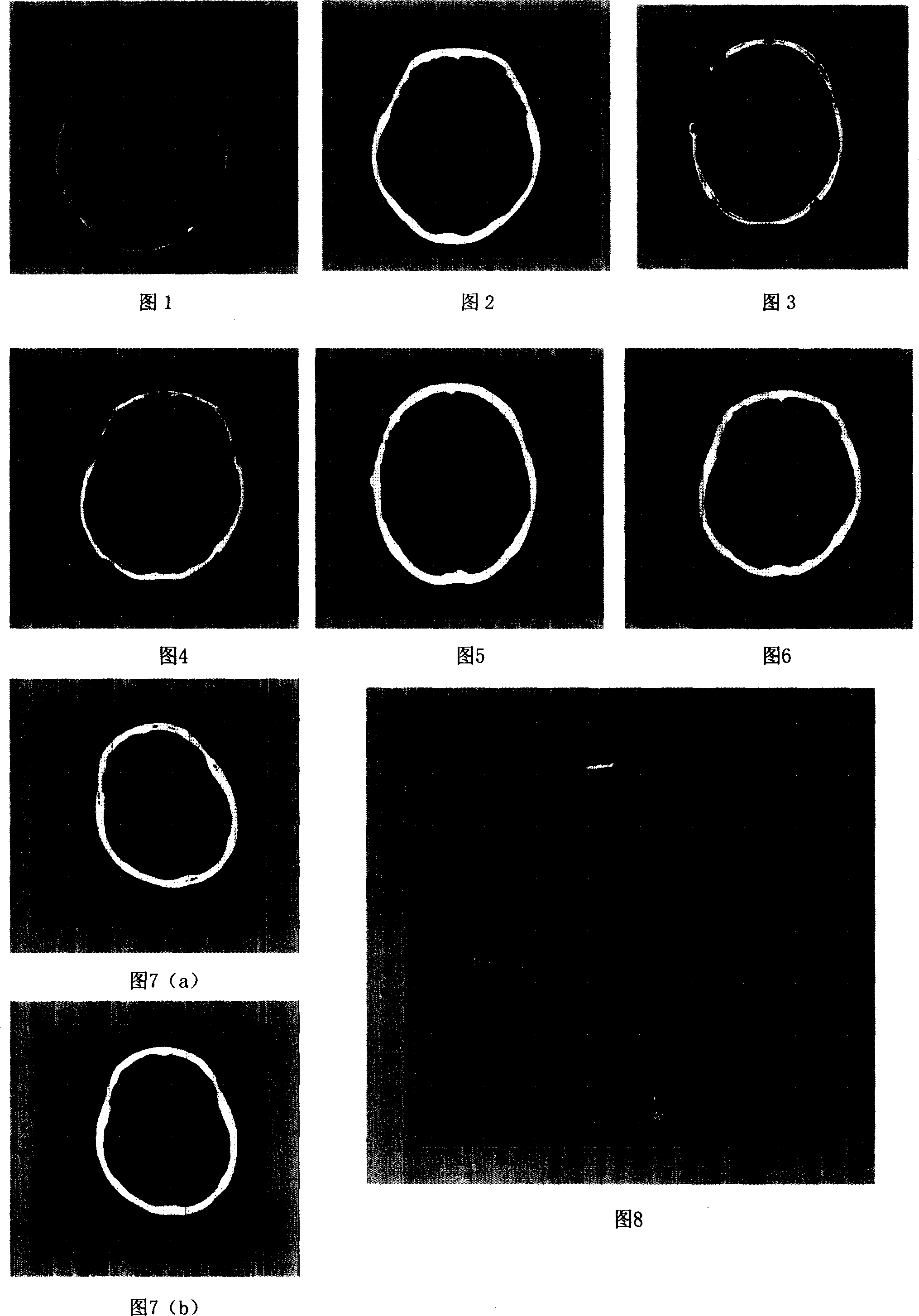
[0014] Samples with no craniofacial bone fracture history, no tumor history, and "normal" brain geometry were selected from the living brain CT scan images taken in the hospital. With the help of CDViewer software, select the CT image of the first layer of the ventricle, adjust the window width and window level to 2000 and 600, so that the bones can be displayed most clearly, and then export and store the image in JEPG format, as shown in Figure 1, for post-processing provide data.

[0015] 2. Image segmentation and binarization

[0016] Read in the preprocessed image in the Matlab software, X is the image data after reading; the given threshold is 0.3, and X is converted into binary image data BW by BW=im2bw(X, 0.3), as shown in Figure 2 Show. BW is a 512×512 matrix with elements 0 or 1;

[0017] 3. Repair the defect contour and remove interference points

[0018] Due to the difference in the skull structure of each pers...


PUM


Abstract

A computer aided measuring method based on the CT image of skull for fast and correctly measuring the thickness of frontal bone, parietal bone and occipital bone includes such steps as writing program, format conversion of the CT image, dividing the image, obtaining the binary data of divided image, repairing the defected profile, removing interference point, correcting the derivation of image, extracting the edge of image, determining the reference point for measurement, and automatic measuring.

Description

technical field [0001] The invention belongs to the technical field of image processing and application, in particular to a computer-aided measurement method based on skull CT images. Background technique [0002] Skull thickness measurement has important application value in research fields such as human anatomy, clinical medicine, and biomechanical simulation of head injury. Commonly used skull measurement tools include straight feet, curved feet, and vernier calipers, but these are suitable for the measurement of specimens, not for the measurement of living data. Contents of the invention [0003] The technical problem to be solved by the present invention is to provide a computer-aided measurement method based on skull CT images. The measurement method processes the CT image of the living human head through a self-compiled calculation program, and realizes the rapid, accurate, large-scale, non-contact and automatic measurement of the thickness of the skull. So as to ...

Claims


Application Information

Patent Timeline
IPC IPC(8): A61B6/02A61B6/03
Inventor 李海岩阮世捷谢中华刘文岭王浩
Owner TIANJIN UNIVERSITY OF SCIENCE AND TECHNOLOGY
Learn More