
An Automatic Range Measuring Method for Measuring Digital Storage Oscilloscope

A technology of automatic range and measurement method, which is applied in the direction of digital variable display, range change circuit, etc., can solve problems affecting production efficiency, achieve fast automatic measurement, save time, and improve work efficiency.

Inactive Publication Date: 2015-11-04
FUJIAN LILLIPUT OPTOELECTRONICS TECH
View PDF10 Cites 0 Cited by
  • Summary
  • Abstract
  • Description
  • Claims
  • Application Information

AI Technical Summary

Problems solved by technology

[0003] For example, it is necessary to test multiple test points during production, and the voltage parameters or frequency parameters of each test point may be different. If the current method is used to test the test points, the voltage gear or time base gear must be manually adjusted. Or press the automatic setting, it will seriously affect the production efficiency,

Method used


Image

  • An Automatic Range Measuring Method for Measuring Digital Storage Oscilloscope
  • An Automatic Range Measuring Method for Measuring Digital Storage Oscilloscope
  • An Automatic Range Measuring Method for Measuring Digital Storage Oscilloscope

Examples


Embodiment Construction

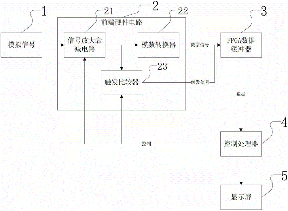
[0048] see figure 1 As shown, an automatic range system for measuring digital storage oscilloscopes includes: FPGA data buffer 3, control processor 4, display 5, and also includes front-end hardware circuit 2, wherein,

[0049] The output end of the front-end hardware circuit 2 is electrically connected to the input end of the FPGA data buffer 3, and the control processor 4 is respectively input to the FPGA data buffer 3, the display 5 and the front-end hardware circuit 2. terminal electrical connection;

[0050] Described front-end hardware circuit 2 further comprises:

[0051] Signal amplification and attenuation circuit 21, used to amplify or attenuate the adopted analog signal;

[0052] Trigger comparator 23, compare according to the signal of described signal amplification attenuation circuit 21 input and the signal that control processor 4 feeds back, generate trigger signal and send to FPGA data buffer 3;

[0053]The analog-to-digital converter 22 is used to convert ...


PUM


Abstract

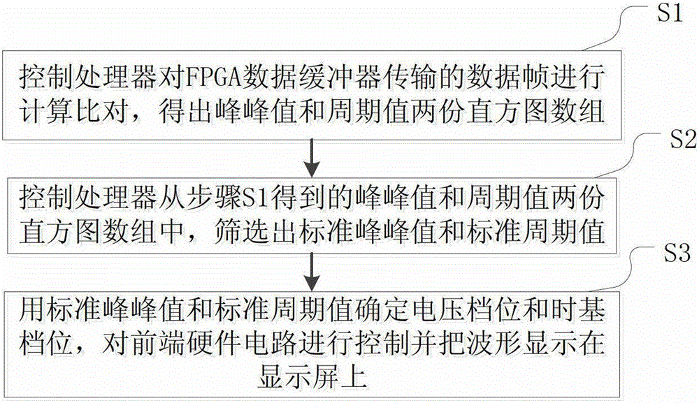
The invention discloses an automatic measuring range system and a measuring method used for measuring a digital storage oscilloscope. The system is characterized in that a front-end hardware circuit is connected with a control processor through an FPGA (field programmable gate array) data buffer, the control processor is respectively connected with the FPGA data buffer, a display and the front-end hardware circuit. The measuring method includes steps: S1, calculating and comparing data frames transmitted by the FPGA data buffer by the control processor to obtain two histogram arrays of peak-to-peak values and period values; S2, screening out a standard peak-to-peak value and a standard period value from the two histogram arrays of the peak-to-peak values and the period values obtained in S1 by the control processor; and S3, using the standard peak-to-peak value and the standard period value to determine voltage gears and time base gears, and controlling the front-end hardware circuit and displaying proper waveforms on the display screen. The oscilloscope automatically adjusts the voltage gears and the time base gears, time is saved, working efficiency is improved, and waveforms can be measured automatically and quickly.

Description

technical field [0001] The invention relates to digital oscilloscope technology, in particular to a processing technology for digital storage oscilloscopes when measuring changing waveforms, in particular to an automatic range measurement method for digital storage oscilloscopes. Background technique [0002] The use of an oscilloscope is relatively professional. Observing a waveform requires a series of adjustments, which is inconvenient to use, and customers who use an oscilloscope tend to make mistakes when using an oscilloscope to adjust parameters, or do not know how to adjust parameters. At present, the oscilloscope basically uses automatic setting to adjust the parameters for the waveform. The automatic setting takes a long time, generally takes 2-3 seconds, and when the waveform is automatically set many times, you must manually press the automatic setting button each time and set the oscilloscope. The measurement parameters are relatively slow in operation and respo...

Claims


Application Information

Patent Timeline
Patent Type & Authority Patents(China)
IPC IPC(8): G01R15/09G01R13/02
Inventor 汤克明吴朝荣薛增鑫陈焕洵
Owner FUJIAN LILLIPUT OPTOELECTRONICS TECH
Learn More