
Internet protocol network end-to-end performance monitoring system and method

A network performance and Internet protocol technology, applied in transmission systems, digital transmission systems, data exchange networks, etc., can solve the problem that the measurement data packets cannot be guaranteed to go back and forth through the same path, the impact of network failure test results cannot be distinguished, and the single To solve problems such as path performance indicators, to achieve the effect of convenient and objective data analysis, reduce impact, and improve test accuracy

Inactive Publication Date: 2007-06-13
INST OF TELECOMM TRANSMISSION MINIST OF INFORMATION IND
View PDF0 Cites 41 Cited by
  • Summary
  • Abstract
  • Description
  • Claims
  • Application Information

AI Technical Summary

Problems solved by technology

[0010] The disadvantages of the above technology are: firstly, this method uses a centralized test network topology, and the central transmitting point not only needs to maintain the transmitting process with all reflection points, but also needs to maintain the receiving process with all reflection points, plus The processing overhead of the monitoring data by the system will inevitably bring large errors to the test accuracy
[0011] Second, the technique uses two-way round-trip RTT for measurements and can only provide round-trip test results
The Internet is a typical packet-switching network, and it cannot guarantee that the measurement data packets go through the same path. Even if they go through the same path, the performance of the two directions may be very different. Performance
In addition, this technology does not analyze abnormal conditions, and cannot distinguish the impact of network failures or reflection point failures on test results

Method used


Image

  • Internet protocol network end-to-end performance monitoring system and method
  • Internet protocol network end-to-end performance monitoring system and method
  • Internet protocol network end-to-end performance monitoring system and method

Examples


Embodiment Construction

[0054] In order to make the object, technical solution and advantages of the present invention more clearly, the present invention will be further described in detail below in conjunction with the accompanying drawings and specific embodiments.

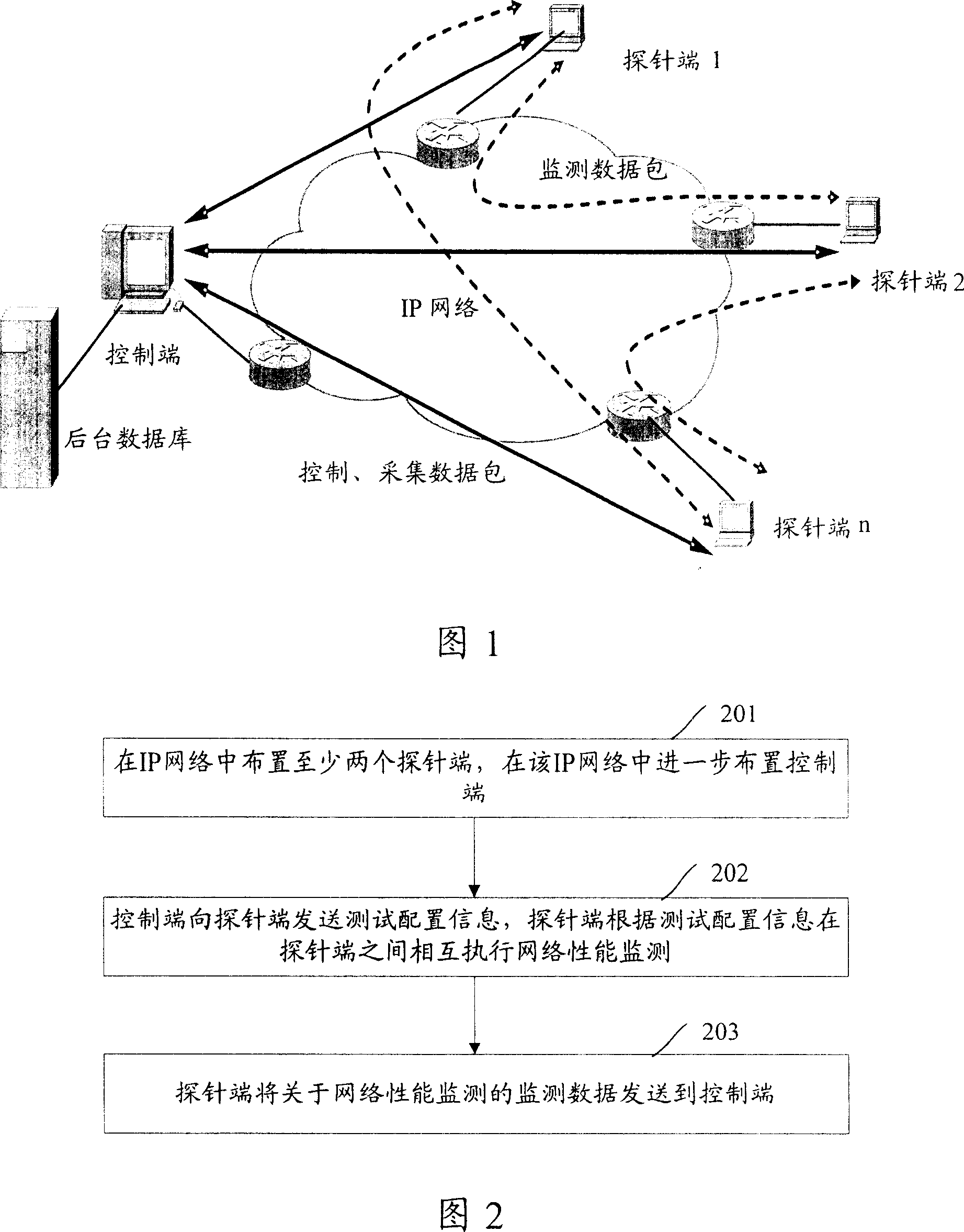
[0055] FIG. 1 is a schematic diagram of an exemplary structure of an IP network end-to-end performance monitoring system according to the present invention. As shown in Figure 1, the IP network performance monitoring system includes a control terminal (Console) and a probe terminal (Probe), wherein the number of probe terminals is at least two, and the number of control terminals can be one or multiple . That is to say, the control mode of the control terminal can be either centralized or distributed.

[0056] In a large network environment, it is preferable to use multiple consoles for distributed control; in a small network environment, it is preferable to use a single console for centralized control. Preferably, in a large-scale ...


PUM


Abstract

The monitoring system includes at least two probe ends located inside IP network, and control end in the IP network. The control end is in use for sending information of test configuration to probe ends, and receiving monitored data about network performance sent from probe ends. Based on information of test configuration to execute monitoring network performance between probe ends, the probe ends are in use for sending monitored data about network performance to the control end. The invention also discloses method for monitoring end-to-end performance of IP network. The invention raises test precision, and obtains accurate, valid monitored data. The measuring mode for testing quality of service in IP network disclosed by the invention is universal, end-to-end, round-the-clock, and diversified.

Description

technical field [0001] The invention relates to the technical field of Internet performance monitoring, in particular to an Internet Protocol (IP) network end-to-end performance monitoring system and method. Background technique [0002] With the rapid development of the Internet based on IP technology, more and more users use the Internet for work and study. The amount of data on the network increases geometrically, which also puts forward higher and higher requirements for the quality of service (QoS) of the network. At present, with the rise of multimedia applications, various services such as IP telephony, video conferencing systems, and video-on-demand have much higher requirements for service quality than traditional applications. Therefore, to use these new services on the Internet, a specific quality of service guarantee mechanism must be provided. [0003] The basic IP protocol provides only one quality of service, that is, "Best-Effort" service. In the best-effo...

Claims


Application Information

Patent Timeline
IPC IPC(8): H04L12/26H04L12/56
Inventor 何宝宏魏亮田辉高巍马科张彤卢彧
Owner INST OF TELECOMM TRANSMISSION MINIST OF INFORMATION IND
Learn More