
Fraction frequency-division circuit applied for phase-locked ring circuit

A fractional frequency division and pre-frequency division circuit technology, applied in the direction of electrical components, automatic power control, etc., can solve problems such as reducing the output frequency resolution, and achieve the effect of suppressing noise

Inactive Publication Date: 2007-06-13
SHANGHAI HUA HONG NEC ELECTRONICS
View PDF0 Cites 0 Cited by
  • Summary
  • Abstract
  • Description
  • Claims
  • Application Information

AI Technical Summary

Problems solved by technology

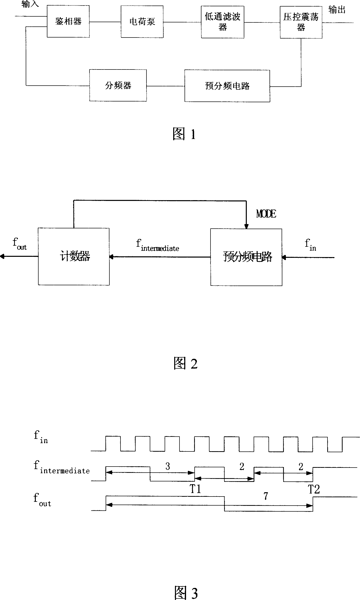
[0004] At the same time, in the field of communication, in order to avoid the use of a very high counting frequency divider, a fixed frequency divider is often connected behind the voltage controlled oscillator, but this reduces the resolution of the output frequency
As shown in Figure 1, the prescaler circuit can ensure the normal operation of the high-frequency phase-locked loop, but because the frequency division number is fixed, the resolution of the output frequency (fo) is reduced

Method used


Image

  • Fraction frequency-division circuit applied for phase-locked ring circuit
  • Fraction frequency-division circuit applied for phase-locked ring circuit
  • Fraction frequency-division circuit applied for phase-locked ring circuit

Examples


Embodiment Construction

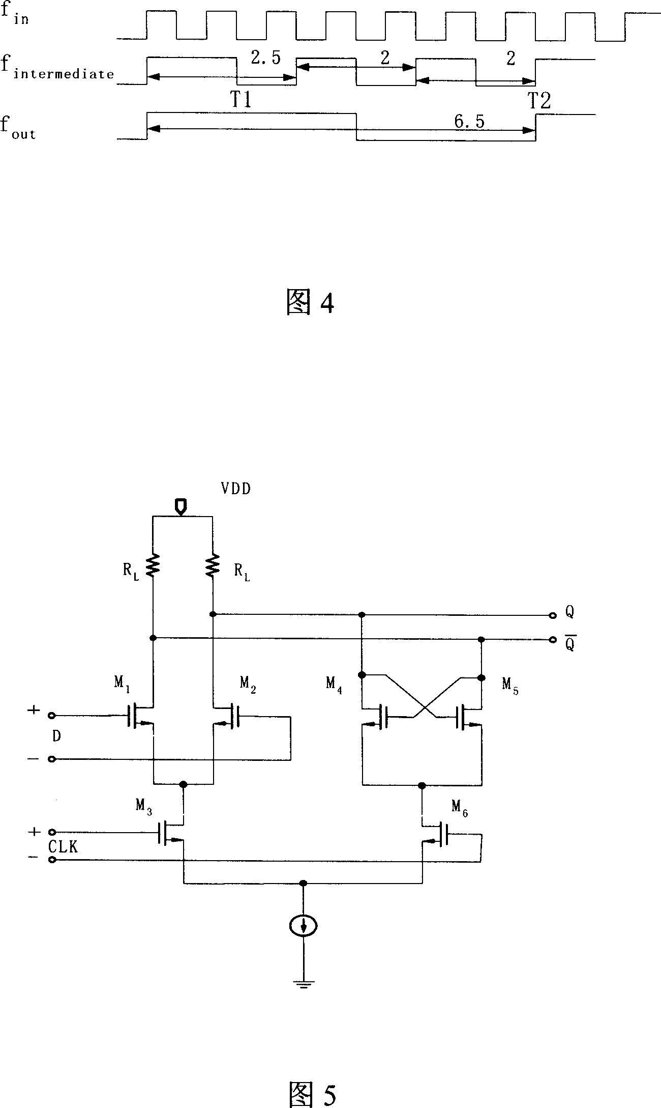
[0018] As shown in Fig. 2, it is a schematic diagram of the fractional frequency division circuit of the present invention. where f in Indicates the input frequency, f out Indicates the output frequency, f intermediate Indicates the frequency obtained by prescaler, and MODE indicates the signal of the control terminal. The circuit is mainly composed of two main modules. The first module is a P / P+1 prescaler circuit, which is composed of a current mode logic circuit (Current Mode Logic). This circuit is characterized by high speed and low noise. The method realizes the function of the digital circuit. When the signal at the control terminal is at a high level, P+1 is used as the modulus to divide the output frequency of the VCO; when the signal at the control terminal is at a low level, the output frequency of the VCO is divided with P as the modulus, and P is a natural number.

[0019] The second module is a programmable counter. Its working principle is: when the system ...


PUM


Abstract

Being applicable to the phase lock ring (PLR) circuit, the fraction frequency dividing circuit uses Hf signal of processing voltage-controlled oscillator (VCO) to raise reference frequency of PLR effectively, and reduce influence noise from signal source without lowering resolution. The fraction frequency dividing circuit includes a pre frequency dividing circuit (PFDC) and a counter. When control end is in high level, PFDC divides frequency of output of VCO in PLR circuit by using modulus P+1, and when control end is in low level, PFDC divides frequency of output of VCO in PLR circuit by using modulus P. the counter works according to following logic: after resetting system, sending a signal in high to control end of PFDC to start counting; when reaching to a prearranged value, sending a signal in low to control end of PFDC; when reaching to another prearranged value, resetting system and counter. In rising edge and falling edge of each clocking, the counter counts.

Description

technical field [0001] The invention relates to a phase-locked loop design in the field of integrated circuit design, in particular to a fractional frequency division circuit applied to a phase-locked loop circuit. Background technique [0002] Phase-locking technology is widely used in the communication field, and the performance requirements are getting higher and higher. As the main part of the frequency synthesizer, the phase noise of the phase-locked loop becomes a very important index, because it determines whether the communication frequency band can be effectively used in a strong interference environment. [0003] In order to get lower phase noise, a broadband PLL can effectively suppress the noise generated from the voltage-controlled oscillator (VCO), but the influence of the reference clock noise generated from the crystal oscillator becomes more important. Compared with narrow-band PLLs, the noise of the reference clock is less likely to be suppressed. [0004...

Claims


Application Information

Patent Timeline
Patent Type & Authority Applications(China)
IPC IPC(8): H03L7/18H03L7/08
Inventor 温建新朱红卫童红亮刘天伟
Owner SHANGHAI HUA HONG NEC ELECTRONICS
Learn More