Color picture tube

A color picture tube and tube axis technology, applied in the field of color picture tubes, can solve the problems that hinder the cost reduction of the reinforcement band 12, and achieve the effects of good color display, improved planarity, and reduced local deformation

Inactive Publication Date: 2007-06-06
MATSUSHITA TOSHIBA PICTURE DIS
View PDF0 Cites 0 Cited by
  • Summary
  • Abstract
  • Description
  • Claims
  • Application Information

AI Technical Summary

Problems solved by technology

Therefore, in the case of flattening the outer surface of the effective portion 1a of the panel 1, a reinforcement tape that generates a large fastening force is required, which prevents cost reduction of the reinforcement tape 12.

Method used


Image

  • Color picture tube
  • Color picture tube
  • Color picture tube

Examples


Embodiment Construction

[0050] Embodiments of the present invention will be described below with reference to the drawings.

[0051] The general structure of the color transistor of the present invention is not particularly limited except for the shapes of the inner and outer surfaces of the panel, and may be the same as the conventional flat tube shown in FIG. 7, for example. Therefore, the present invention will be described below focusing on points different from conventional flat tubes.

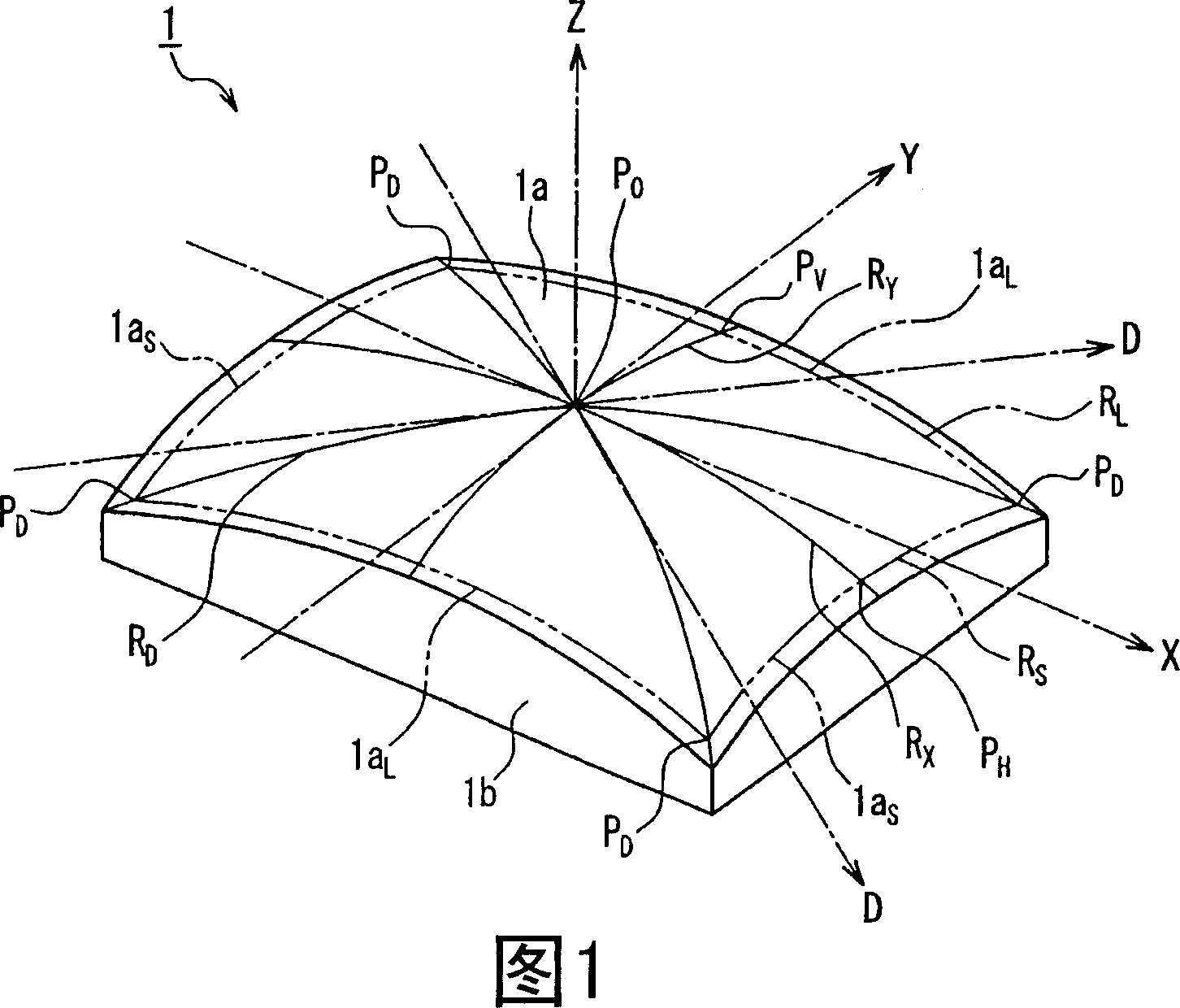
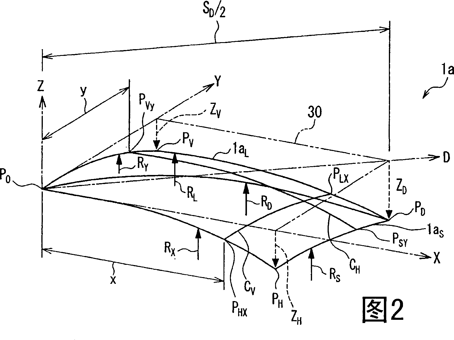
[0052] The outer surface of the effective portion 1a of the color transistor panel 1 of the present invention is formed as a curved surface having a large curvature radius that can be recognized as a substantially flat surface when viewed from a distance, and the inner surface of the effective portion 1a is formed to have a predetermined curvature radius. Concave surfaces. A substantially rectangular phosphor screen 3 is formed on the inner surface of the panel 1 . In the present invention, the region on the i...


PUM


Abstract

The radii of curvature RD, RS and RL along a diagonal axis, a short side and a long side of an outer surface of a useful portion of a panel whose inner surface is provided with a phosphor screen satisfy RD>=10 m, RS>RD, and RL>RD. This makes it possible to provide a color picture tube that has an excellent visibility and is not susceptible to the deterioration in color purity due to doming, while including a shadow mask with excellent formability and strength.

Description

technical field [0001] The present invention relates to a color picture tube provided with a shadow mask. Background technique [0002] Generally, as shown in FIG. 7, a color picture tube has a glass peripheral device 9 composed of a substantially rectangular panel 1 and a funnel-shaped funnel cover 2 joined to a side wall 1b. The periphery of the portion 1a is provided with a side wall portion 1b. On the inner surface of the effective part 1a of the panel 1, there are provided a black non-luminescent material layer and a substantially rectangular phosphor composed of green, blue and red phosphors embedded in the gap between the black non-luminescent material layers. body screen3. Each phosphor is formed in a stripe shape along the short side direction, and a plurality of stripes of the phosphors are arranged along the long side direction. [0003] A shadow mask structure 5 is provided to face the phosphor screen 3 . The shadow mask structure 5 is composed of a shadow ma...

Claims


Application Information

Patent Timeline
Patent Type & Authority Applications(China)
IPC IPC(8): H01J29/86
Inventor 村井敬小岛忠洋中山刚士濑户信行
Owner MATSUSHITA TOSHIBA PICTURE DIS
Why Eureka
Try Eureka