Method and device for measuring transverse pressure in powder warm flow compaction
A transverse pressure and warm pressure forming technology, applied in the field of material processing, can solve the problems of manufacturing technology and its process principle research that have not yet been reported, and achieve the effects of intuitive measurement method, wide application range and easy operation.
- Summary
- Abstract
- Description
- Claims
- Application Information
AI Technical Summary
Problems solved by technology
Method used
Image
Examples
Embodiment 1
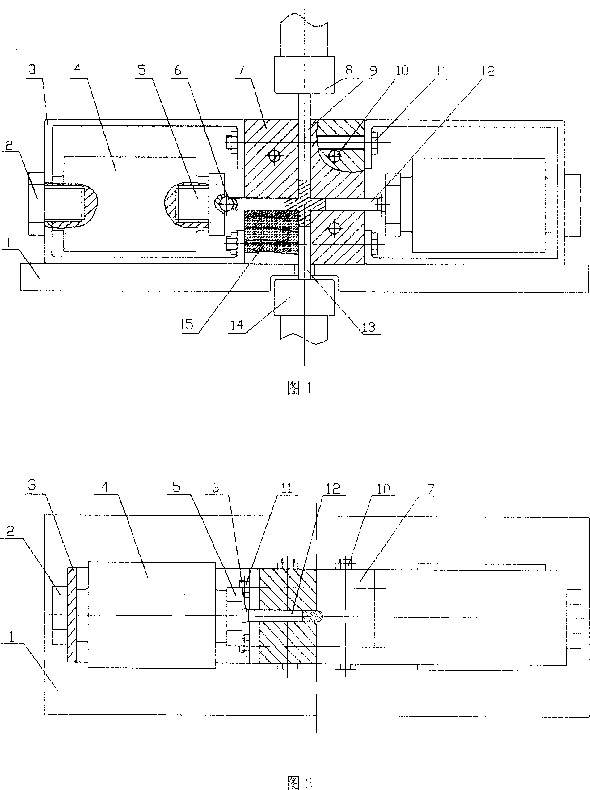
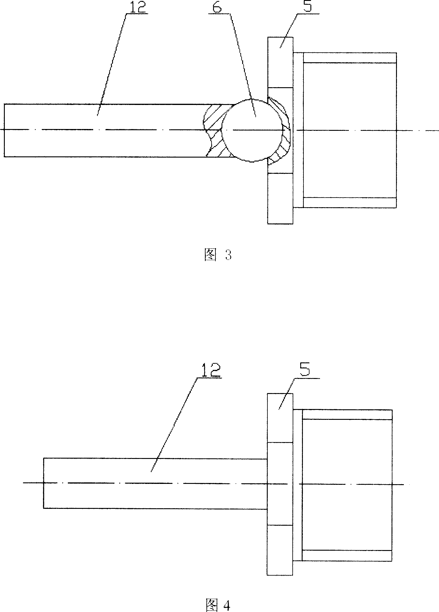
[0022] As shown in Fig. 1 and Fig. 2, the lateral pressure measuring device for powder flow warm pressing is composed of two ejector rods 12, two steel balls 6, two upper and lower die punches 9, 13, and two spiral ejector columns 5 installed symmetrically. , two sensor fixing brackets 3, two fixing bolts 2, two pressure sensors 4, a cross mold 7 that can be split and closed, a heating device 15, and a data acquisition card. As shown in Figure 3, it is a schematic structural diagram of the ejector rod and the screw ejector column connected by steel balls for the measuring device of the transverse pressure of powder flow warm pressing. Clamp the two cross-shaped molds 7 with four sets of bolts 10, and fix the two sensor holders 3 on both sides of the mold cross-shaped mold 7 with four sets of bolts 11; Insert the transverse mold cavity matched with the ejector rod 12 on both sides, screw the two screw ejector columns 5 into the threaded connection holes of the measuring end of ...
Embodiment 2
[0027] As shown in Fig. 4, in this device, the ejector rod 12 is directly connected with the screw ejector column 5, that is, it is not connected through steel balls. The end face of the push rod 12 is flat and cooperates with the screw top column 5 whose end surface is also flat; the screw top column 5 is connected with the pressure sensor 4 . This embodiment requires that the verticality between the end face of the ejector rod 12 and the centerline of the spiral ejector column 5 and the perpendicularity between the end surface of the spiral ejector column 5 and the center line of the spiral ejector column 5 reach more than 7 levels of perpendicularity, which can avoid causing the ejector rod Tilt to meet the test conditions. In this way, the change of the lateral pressure can also be displayed continuously and directly on the indicator connected to the pressure sensor 4 . All the other implementations are the same as in Example 1.
PUM
| Property | Measurement | Unit |
|---|---|---|
| diameter | aaaaa | aaaaa |
Abstract
Description
Claims
Application Information
 - Generate Ideas
- Intellectual Property
- Life Sciences
- Materials
- Tech Scout
- Unparalleled Data Quality
- Higher Quality Content
- 60% Fewer Hallucinations
Browse by: Latest US Patents, China's latest patents, Technical Efficacy Thesaurus, Application Domain, Technology Topic, Popular Technical Reports.
© 2025 PatSnap. All rights reserved.Legal|Privacy policy|Modern Slavery Act Transparency Statement|Sitemap|About US| Contact US: help@patsnap.com


