
Magnetic induction loop scoring system for target

A technology of magnetic induction coils and darts, which is applied in the field of configuration of magnetic induction coils, can solve problems such as waste of materials and wires of induction detection coils 11, complicated assembly and matching components and technologies, and complicated assembly methods, so as to reduce the complexity of circuit coil winding The effect of reducing the complexity of winding and simplifying the assembly work

Inactive Publication Date: 2007-05-30
游志豪
View PDF1 Cites 2 Cited by
  • Summary
  • Abstract
  • Description
  • Claims
  • Application Information

AI Technical Summary

Problems solved by technology

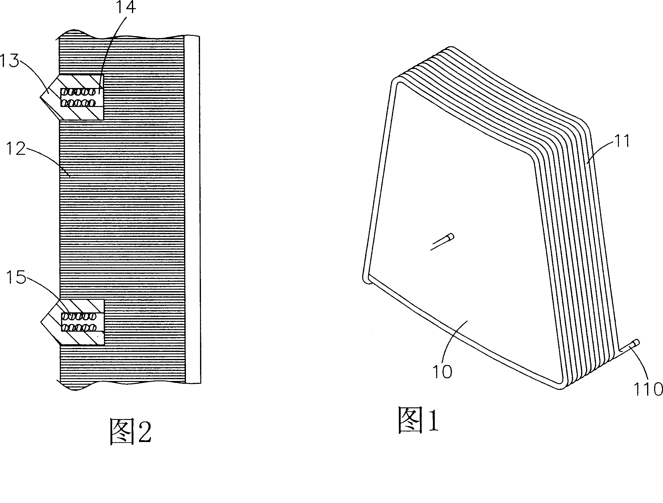
[0008] One, the multiple induction coils 15 of this prior art dart board must be coiled and assembled for each scoring area equally, so a very large number of induction coils 15 will be configured on a dart board (each scoring area There is a set of induction coils and two signal terminals in the area), and the assembly method of this improved product is still complicated, and there are too many loop coils. In order to allow many signal terminals to smoothly connect with the electronic scoring components, it also requires complicated assembly. components and technologies;
[0009] Its two, in its scoring area target frame 13, be equipped with multiple induction detection coils 11, each adjacent induction detection coils 11 will not only overlap and arrange, and form the induction detection coils 11 material wire rod waste and cost relatively high problem, and the stacking operation also causes a burden on the operation

Method used


Image

  • Magnetic induction loop scoring system for target
  • Magnetic induction loop scoring system for target
  • Magnetic induction loop scoring system for target

Examples


Embodiment Construction

[0044] For the present invention to achieve the above-mentioned purpose, the technology adopted, means and other effects, hereby enumerate a preferred embodiment and cooperate with the drawings to describe in detail as follows. It is believed that the purpose, characteristics and other advantages of the present invention should be obtained by it. a deep and specific understanding;

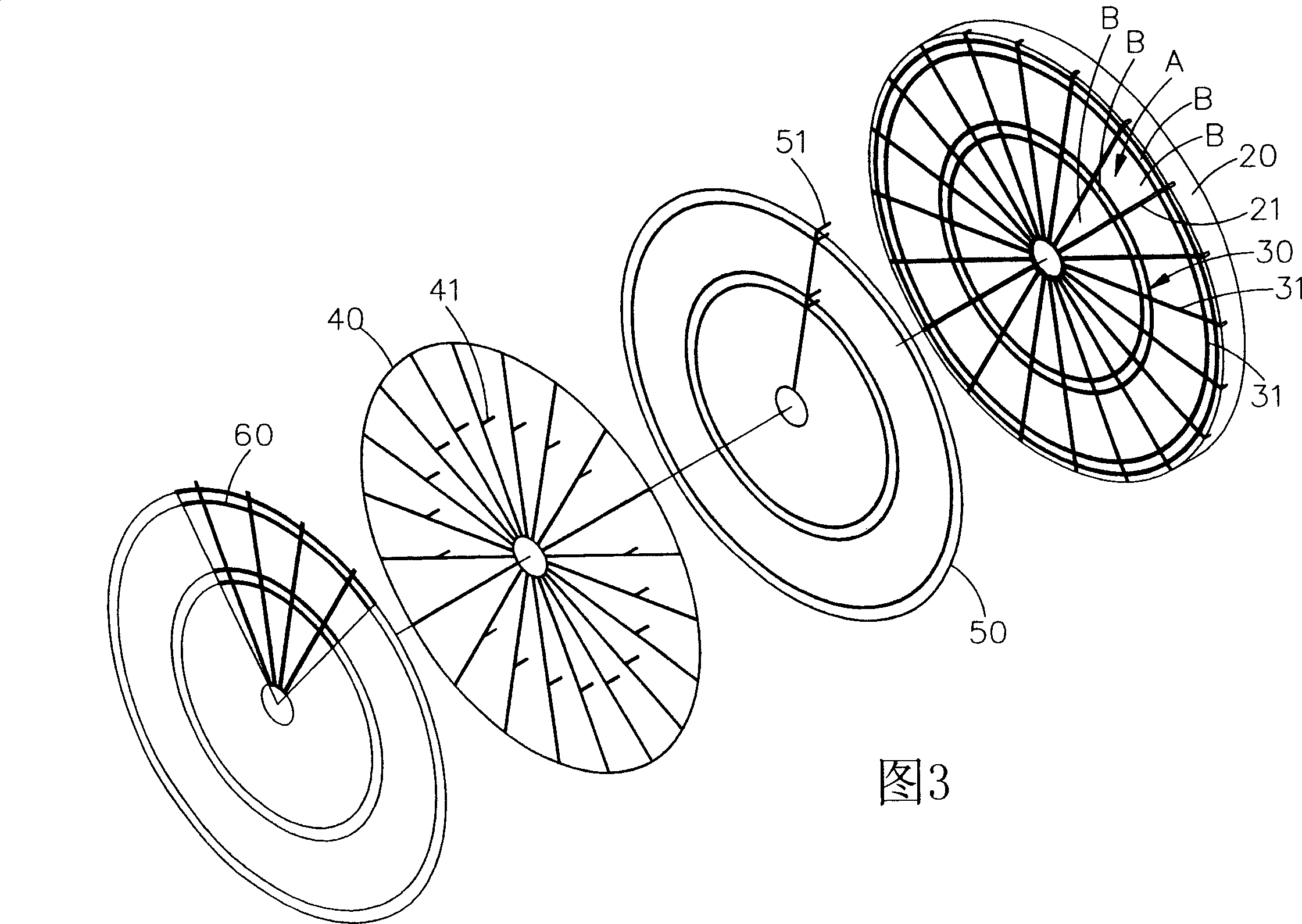
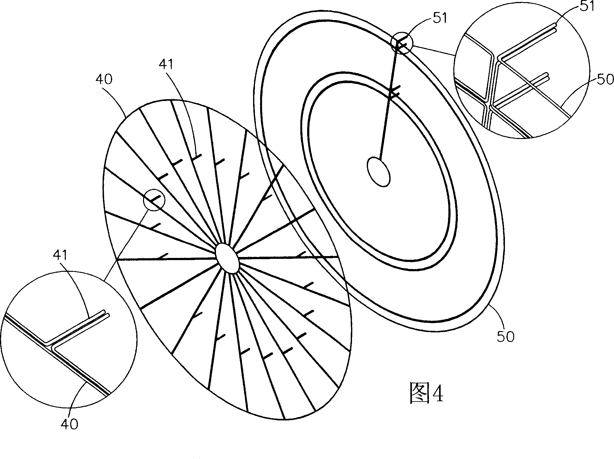
[0045] Please refer to the exploded view and cross-sectional view of the structure of the present invention shown in Fig. 3 and Fig. 4, and refer to the embodiments for detailed description as follows: the present invention includes a target body 20, a frame 30, a fan-shaped magnetic induction coil circuit 40, and an arc-shaped magnetic induction coil circuit 50. The metal cover 60 and the electronic scoring unit 70 are matched with a magnetically sensitive dart to carry out the scoring operation of shooting darts. The frame 30 and the metal cover 60 in this preferred embodiment are not the essentia...


PUM


Abstract

The invention relates to a scoring system of magnet sensible coil for dart target. Several magnet sensible coil circuits and electric scoring cell are set on the dart target. According to the equal region of the radiation wire direction the dart target divides into several pie slices and each pie slice divides into several scoring region according to relative region of presetting concentric circle direction. A sector magnet sensible coil circuit is set relative to each pie slice. The arc magnet sensible coil circuit has at least two scoring region corresponding to the same path around and it is crossed with the sector magnet sensible coil circuit. By above mentioned magnet sensible coil circuit matching with electric scoring cell score at each scoring region are carried out and after electric scoring cell receives signals from sector magnet sensible coil circuit and are magnet sensible coil circuit, it can locate the scoring region of dart and calculate the score of dart. In addition, the invention can decrease the number of magnet sensible coil circuit and the length of coil greatly, simplify the installing work effectively, decrease the winding complication of electric coil, and reduce the working cost fully.

Description

technical field [0001] The invention relates to a configuration of magnetic induction coils, in particular to a configuration system for automatic scoring using magnetic induction coils on a dart board, which can indeed reduce operating costs and product costs. Background technique [0002] Today's darts are already a modern emerging competition and entertainment, and the demand for technical improvement of dartboard equipment has been continuously generated. In response to the constant innovation and change of product design in the market, various electronic magnetic dartboard equipment has been developed. It has become one of the mainstream commodities in the market. Although various magnetic induction dart boards have been used as competition equipment or entertainment products on the market, how to develop magnetic induction scoring dart boards with lower cost and strong price competitiveness is still a challenge. It is still the focus of industry research and developmen...

Claims


Application Information

Patent Timeline
Patent Type & Authority Applications(China)
IPC IPC(8): F41J5/04
Inventor 游志豪
Owner 游志豪
Learn More