
PCB hollow coil current-sensing device

A current sensor and air-core coil technology, applied in the direction of inductors, voltage/current isolation, circuits, etc., can solve the problems of low anti-interference ability and low precision, and achieve the effect of facilitating mass production, ensuring measurement accuracy, and fine manufacturing process

Inactive Publication Date: 2012-06-27
MILUO TONGBIAN ELECTRIC CO LTD
View PDF0 Cites 0 Cited by
  • Summary
  • Abstract
  • Description
  • Claims
  • Application Information

AI Technical Summary

Problems solved by technology

[0006] In order to solve the problems of low precision and low anti-interference ability in existing current sensors, the present invention provides a PCB-type air-core coil current sensor with simple structure, high linearity and strong anti-interference ability

Method used


Image

  • PCB hollow coil current-sensing device
  • PCB hollow coil current-sensing device
  • PCB hollow coil current-sensing device

Examples


Embodiment Construction

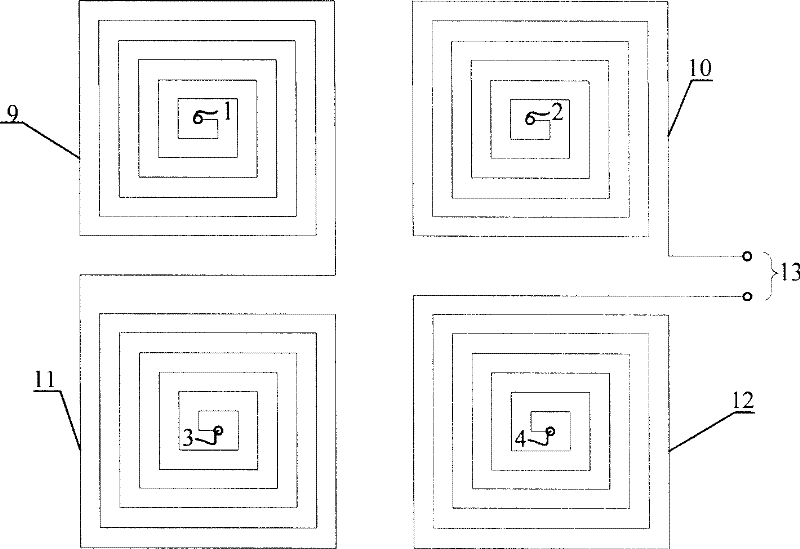
[0021] see figure 1 , figure 1 It is the wiring diagram on the top layer of the PCB current sensor. 9, 10, 11, and 12 are the spiral coils formed by the printed lines on the PCB, and they are evenly distributed around a center; 1, 2, 3, and 4 are the coils on the PCB. The via holes are connected to the upper and lower spiral coils, and 13 is the output end of the sensing coil (the secondary output end of the PCB type air-core coil current sensor). When the interfering alternating magnetic field at the far end passes through the sensing coil of this layer, the induced electromotive forces generated by the two helical coils 9 and 11 are equal in size and opposite in direction, and they are connected in series to cancel each other out, and the induced electromotive forces generated by 10 and 12 will also Also cancel each other out.

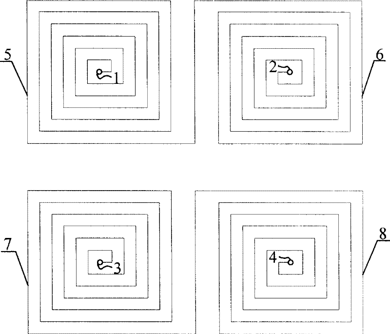
[0022] figure 2 It shows the above-mentioned winding diagram on the bottom layer of the PCB current sensor. Similarly, 5, 6, 7, and 8 are all sp...


PUM


Abstract

The invention discloses a PCB hollow coil current sensor, with one or more layers PCB circuit boards, and each PCB board has even number, four or bigger, uniform plane spiral coil, every PCB board spiral coil distributing symmetrical, and each level adjacent spiral coil serial connects, the spiral coil between layer and layer connecting through cross-hole, and the first and last two ends as the output ends, to constitute the second coil; the first coil tightly winding each half of spiral coils without mutual adjacent to constitute one-cycle or multi-cycle loop. The invention can avoid the external electromagnetic interference, while the second coil can sensitively respond the current of the first coil, and produce the voltage signal proportional to the measured current change rate, and ithas very good linearity and measurement precision, and strong electromagnetic interference resistance ability, suitable for electronic power meters and the current sensor for computer protection and measurement devices.

Description

technical field [0001] The invention relates to a current sensor, in particular to a PCB type hollow coil current sensor. Background technique [0002] Current sensors are commonly used in electronic energy meters and relay microcomputer protection devices to measure current. The current sensors used include mainly small electromagnetic current transformers, small resistance current bypass sensors and Hall effect sensors. When the electromagnetic current transformer measures a large or small current, due to the influence of the excitation current, large numerical errors and phase angle errors will occur. In addition, the ferrite material used in the iron core will be saturated under high current, and the iron core will also produce hysteresis after magnetization. Unless it is demagnetized again, the accuracy will decrease. Therefore, when a small electromagnetic current transformer is used for current measurement, its measurement accuracy is low, especially if the current i...

Claims


Application Information

Patent Timeline
Patent Type & Authority Patents(China)
IPC IPC(8): G01R15/18H01F38/28
Inventor 周有庆龚伟吴桂清彭红海
Owner MILUO TONGBIAN ELECTRIC CO LTD
Learn More