
Linear compressor

A linear compressor, suction valve technology, applied in mechanical equipment, machines/engines, liquid variable capacity machinery, etc., can solve the problems of reducing the diameter of the piston 20, increasing the fluid resistance, and difficult to fix the suction valve 22, etc. Smaller effects of reducing dead volume, reducing fluid resistance, deformation or damage

Inactive Publication Date: 2007-05-23
LG ELECTRONICS INC
View PDF0 Cites 2 Cited by
  • Summary
  • Abstract
  • Description
  • Claims
  • Application Information

AI Technical Summary

Problems solved by technology

However, the use of carbon dioxide working fluid requires a relatively reduced diameter of the piston 20
Thus, in this case, it is difficult to fix the suction valve 22 to the piston 20 with the bolt B, and the piston 20 has to bear increased fluid resistance.

Method used


Image

  • Linear compressor
  • Linear compressor
  • Linear compressor

Examples


Embodiment Construction

[0054] Preferred embodiments of the present invention will be explained below with reference to the accompanying drawings.

[0055] FIG. 4 is a sectional view showing a linear compressor according to a first embodiment of the present invention. FIG. 5 is an exploded perspective view showing a suction valve and a piston included in the linear compressor according to the first embodiment of the present invention. 6 to 9 are views sequentially showing an initial retreat state, a fully retracted state, an initial forward state, and a fully advanced state of the piston of the linear compressor according to the first embodiment of the present invention.

[0056] As shown in FIGS. 4 to 9 , the linear compressor according to the first embodiment of the present invention includes: a housing 50 configured to allow the introduction and discharge of working fluid; a cylinder block 60 and a rear cover 62 disposed in the housing 50 ; And a compression unit P disposed between the cylinder b...


PUM


Abstract

Disclosed herein is a linear compressor in which a piston reciprocally moves in a cylinder upon receiving a reciprocating drive force of a linear motor to compress working-fluid, for example, refrigerant, received in the cylinder. The linear compressor comprises a piston adapted to reciprocally move in a cylinder, the piston being internally formed with a suction path, and a suction valve inserted in the suction path of the piston to move relative to the suction path, the suction valve performing opening / closing operations as it moves relative to the piston when the piston reciprocally moves. With this configuration, the suction valve always exhibits an even stroke, achieving an improvement in response and durability and minimizing vibration and noise due to the opening / closing operations thereof.

Description

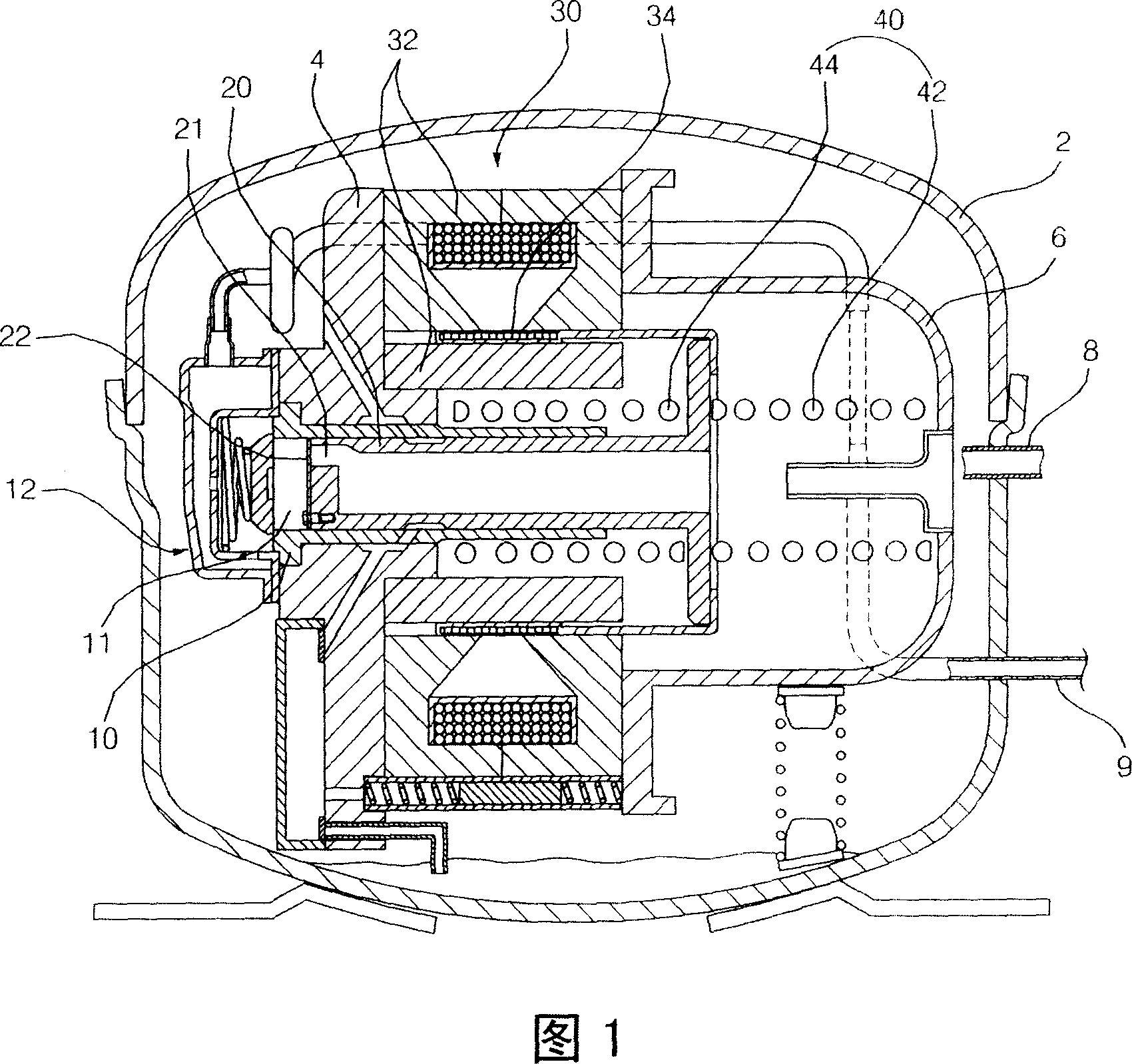
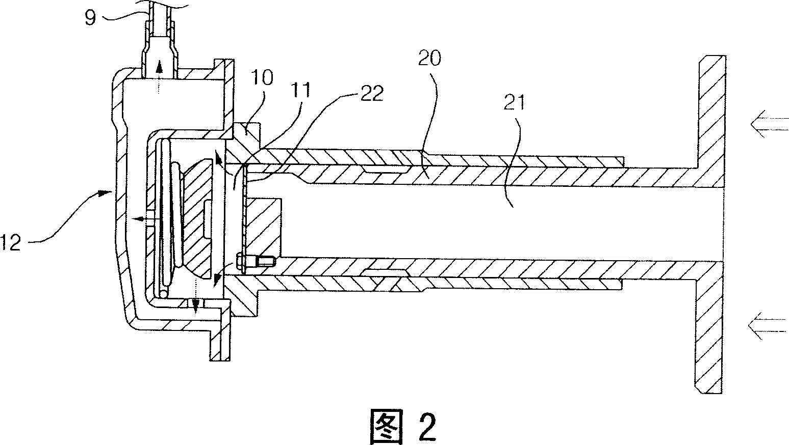
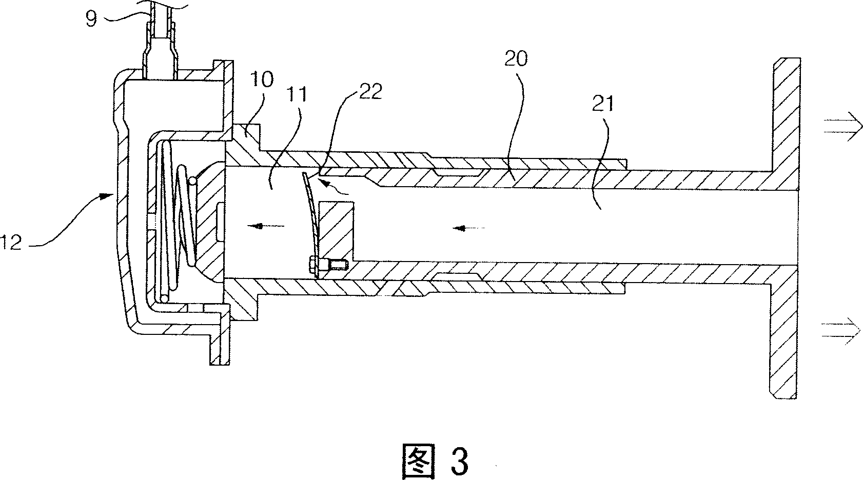
technical field [0001] The present invention relates to a linear compressor, and more particularly, to a linear compressor in which a suction valve moves relative to a piston due to inertial force when the piston reciprocates, thereby performing an opening / closing operation. Background technique [0002] In general, a linear compressor is a device configured in such a way that a piston reciprocates in a cylinder after receiving a reciprocating driving force of a linear motor to compress a working fluid such as refrigerant accommodated in the cylinder. Linear compressors are mainly used in appliances such as refrigerators. [0003] FIG. 1 is a sectional view showing a conventional linear compressor. Fig. 2 is a view of important parts of a conventional linear compressor, showing the forward movement of the piston. Fig. 3 is a view of important parts of a conventional linear compressor, showing the retraction movement of the piston. [0004] As shown in Figures 1 to 3, a co...

Claims


Application Information

Patent Timeline
Patent Type & Authority Applications(China)
IPC IPC(8): F04B39/10F04B35/04
CPCF04B39/0016F04B35/045
Inventor 朴弘熙黄善雄崔基哲
Owner LG ELECTRONICS INC
Learn More