
High molecule polymer diversion and rotation device

A technology of high-molecular polymer and rotating device, which is applied in the field of devices of uniform internal temperature of high-molecular polymer, can solve the problem of not solving the anisotropy of physical properties of products, and achieve the effect of improving the anisotropy

Active Publication Date: 2007-05-16
佛山市顺德区震德塑料机械有限公司
View PDF1 Cites 2 Cited by
  • Summary
  • Abstract
  • Description
  • Claims
  • Application Information

AI Technical Summary

Problems solved by technology

[0004] In the published patent: Application No. 94190758.9 Sushe Chemical Technology Co., Ltd. "Homogenization Device for High Viscosity Fluid", it describes the effect of its invention device on temperature and dispersion of pigments or additives for high viscosity fluids, but does not solve the product There is a problem of obvious anisotropy in physical properties

Method used


Image

  • High molecule polymer diversion and rotation device
  • High molecule polymer diversion and rotation device

Examples


Embodiment Construction

[0017] The present invention will be further described below in conjunction with the accompanying drawings and embodiments.

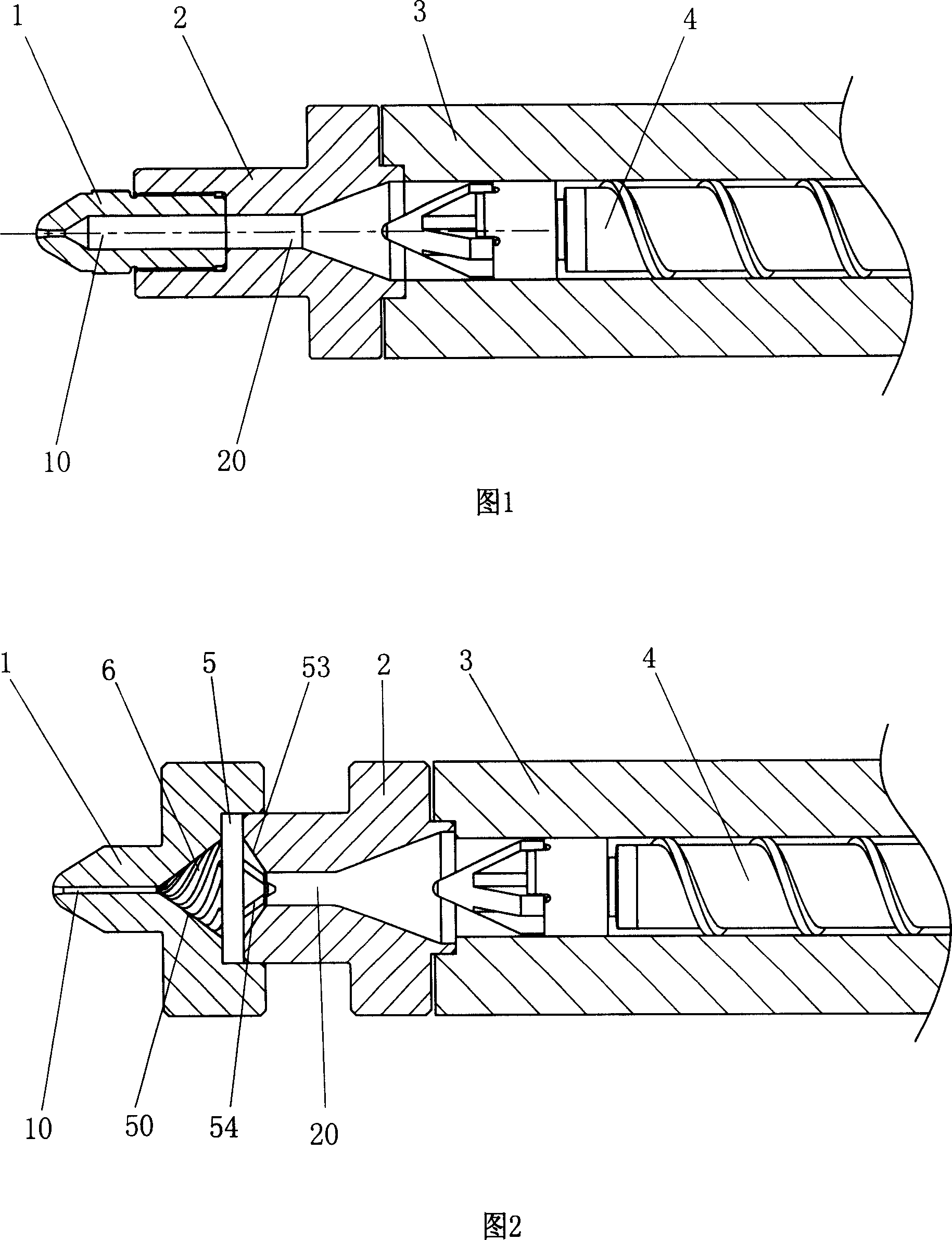
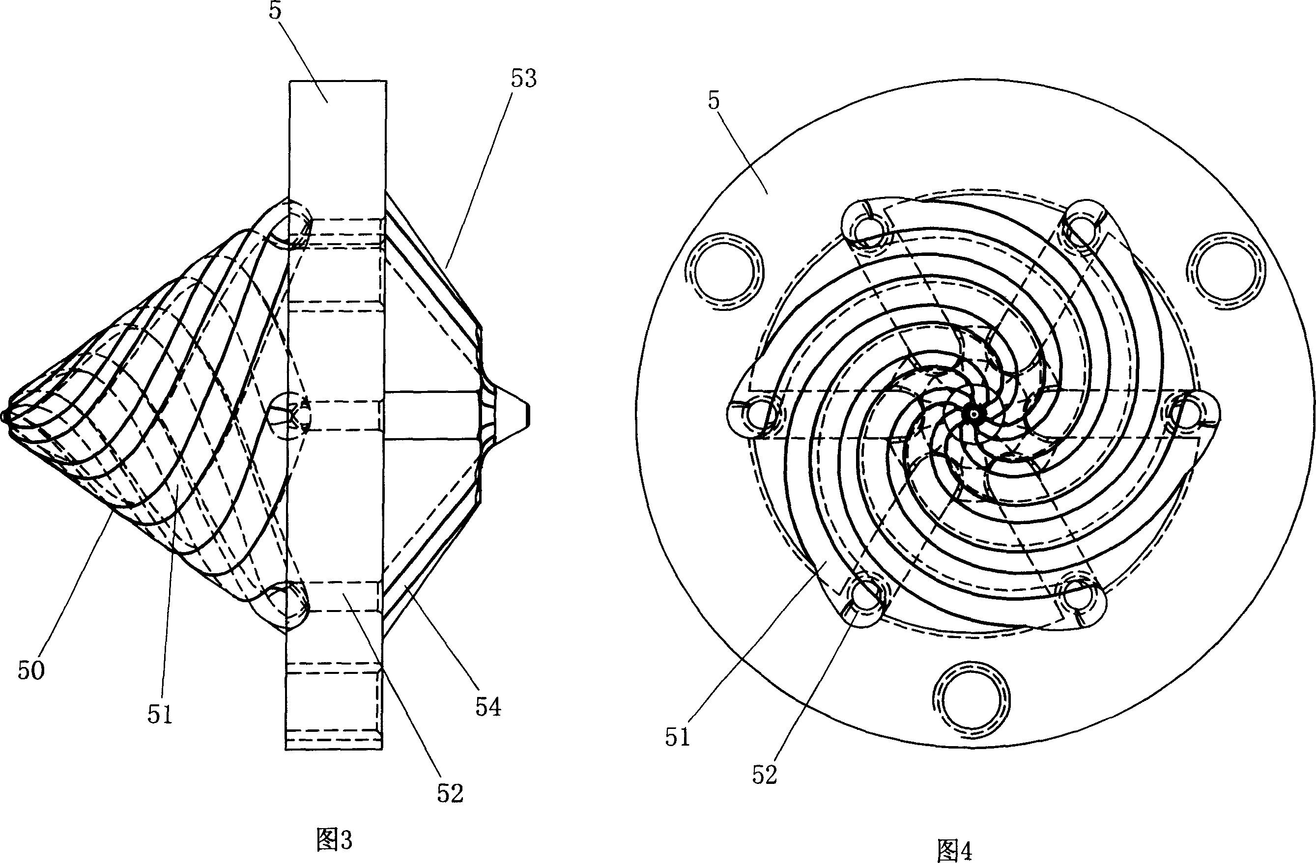
[0018] Referring to Fig. 2 to Fig. 4, a kind of high molecular polymer flow splitting rotating device comprises flange 2, nozzle 1 and main body part 5, and between nozzle 1 and main body part 5, a first conical mating surface 50 and several A spiral flow channel 6 guided by the first conical fitting surface 50, the two ends of the spiral flow channel 6 communicate with the flange 2 and the flow channels (20, 10) of the nozzle 1 correspondingly. The number of said spiral flow channels 6 is at least two. The number of present embodiment is 6.

[0019] The spiral flow channel 6 is matched by several spiral grooves 51 guided by the first conical mating surface 50 that are correspondingly arranged on the main body part 5 or paired on the nozzle 1 and the main body part 5 at the same time. One end of each groove communicates with the flow channel 20 of the...


PUM


Abstract

The invention relates to a device for reducing the transmission resistance of macromolecule polymer and making the internal temperature uniform, wherein the invention is characterized in that: it comprises flange, nozzle and main body; there is the first taper match surface and several screw channels between the nozzle and main body; two ends of screw channel are though to the nozzle. The invention can be mounted at the head of injection to divert, collect and rotate the macromolecule polymer, to make the temperature uniform and disperse paint or additive uniformly; and since the material is rotated in chamber, the molecule chain will be screwed, to improve the physical property.

Description

Technical field [0001] The invention relates to the injection process of an injection molding machine, in particular to a device for reducing the conveying resistance of high molecular polymer and uniform internal temperature of high molecular polymer during the conveying process. Background technique [0002] Injection process of conventional injection molding machine: Use the screw to plasticize the material, and directly extrude it into the mold cavity through the screw or plunger. As shown in Figure 1, the injection structure of an ordinary injection molding machine is shown. Its working principle is: the plastic is plasticized and stored in the barrel 3 at the front end of the screw through the screw part 4, and the external force is applied to the screw 4, and the screw 4 pushes the material stored in the barrel. Material, the material is injected into the mold cavity through the flow channel 20 in the flange 2 and the flow channel 10 in the nozzle 1. When the materia...

Claims


Application Information

Patent Timeline
Patent Type & Authority Applications(China)
IPC IPC(8): B29C45/58B29C45/46B29C45/17
Inventor 谭树发张贤宝
Owner 佛山市顺德区震德塑料机械有限公司
Learn More