
Automatic foam cutting machine and cutting method

A cutting method and cutting machine technology, applied in the direction of metal processing, etc., can solve the problems of laboriousness, difficulty, and no replacement of special equipment, etc., and achieve the effect of convenient and rapid cutting, accurate and reliable operation of equipment, and adjustable working force

Inactive Publication Date: 2007-05-16
张景远
View PDF0 Cites 4 Cited by
  • Summary
  • Abstract
  • Description
  • Claims
  • Application Information

AI Technical Summary

Problems solved by technology

[0002] In the previous "one-step" foam jacket forming line for steel pipes, the last process was to manually cut a small section (about 15cm) of the foam jacket layer at the joint of the steel pipe with a knife, and then the connection between the steel pipes could be removed. Plugs, so that the finished steel pipes with foam jackets are separated from the operation line one by one and transported away; this process of manually cutting the foam jackets of steel pipes, the most laborious, must be cut in the radial direction for at least three weeks , that is, every week, the knife must be radially inserted into the foam jacket layer and then rotated to cut 360 degrees. It is very difficult and obviously tense to cut like this for three weeks, and it must also move along with the pipeline advancing on the line. But for a long time, only The fundamental reason is that there is no special equipment to replace this manual operation.

Method used


Image

  • Automatic foam cutting machine and cutting method
  • Automatic foam cutting machine and cutting method
  • Automatic foam cutting machine and cutting method

Examples


Embodiment Construction

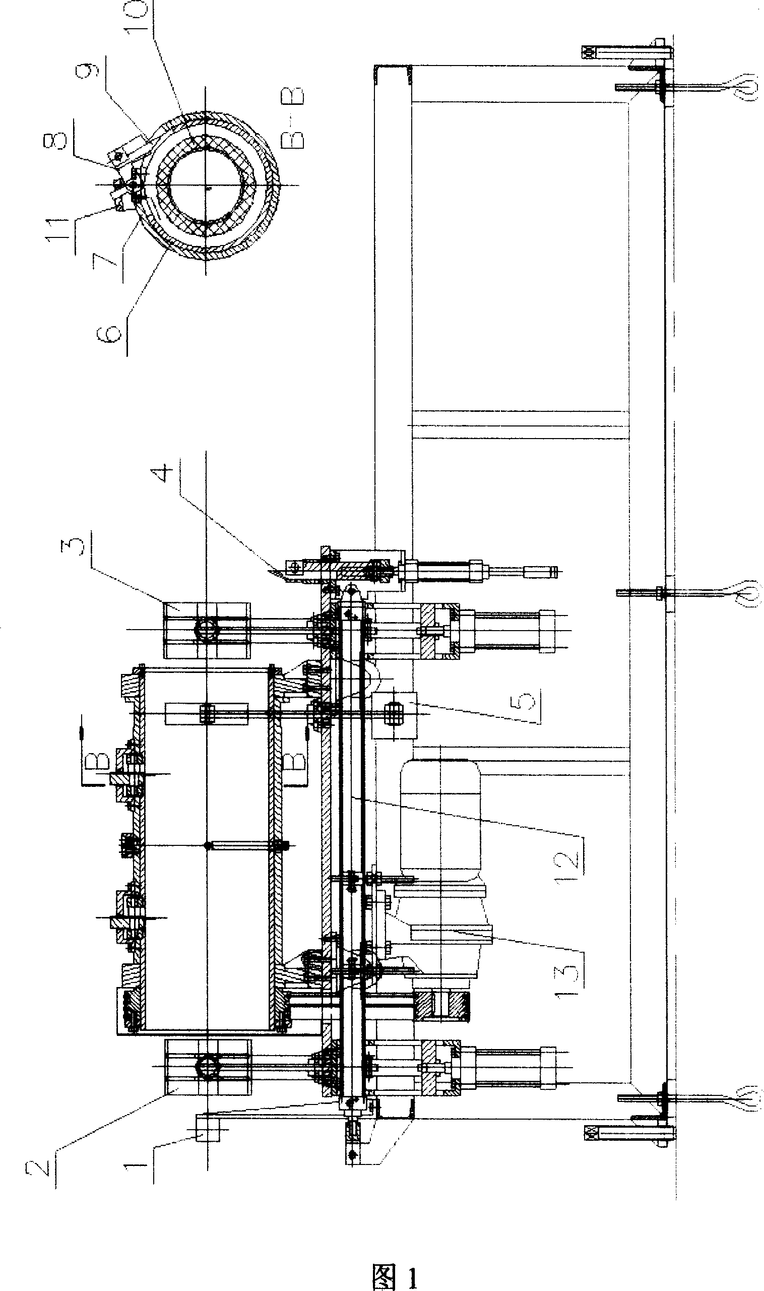
[0036] As shown in FIG. 1 , it is a structural diagram of the automatic foam jacket cutting machine according to the embodiment of the present invention. Including: steel pipe joint detector 1, clamps 2, 3, slitting knife 4, damping device 5, inner cylinder 6, outer cylinder 7, tool holder 8, ring cutter 9, online foam jacket tube 10, dead iron 11 , Cutting trolley 12 , motor 13 , connecting piece 14 , grab hook 15 , rocker arm manipulator 16 .

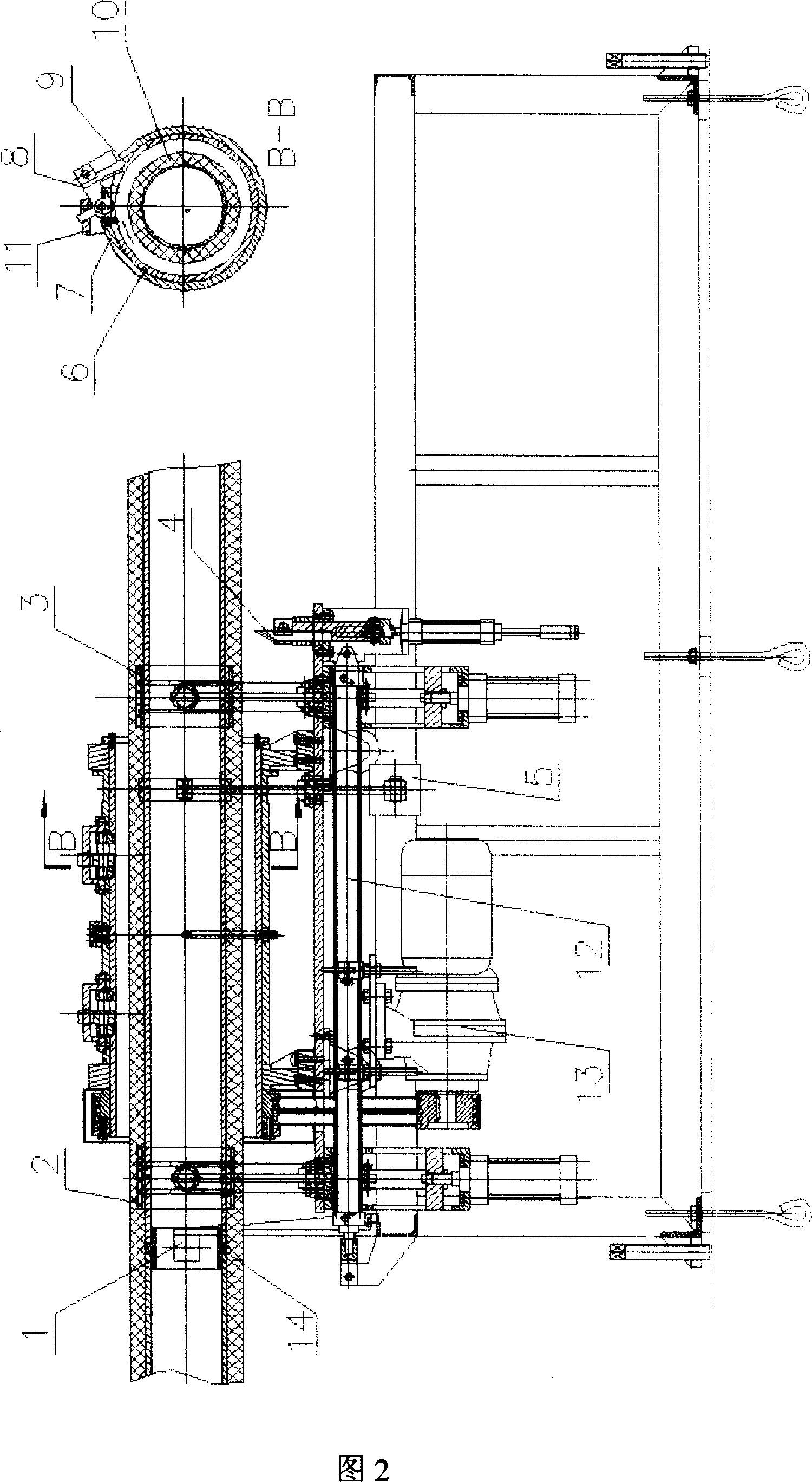
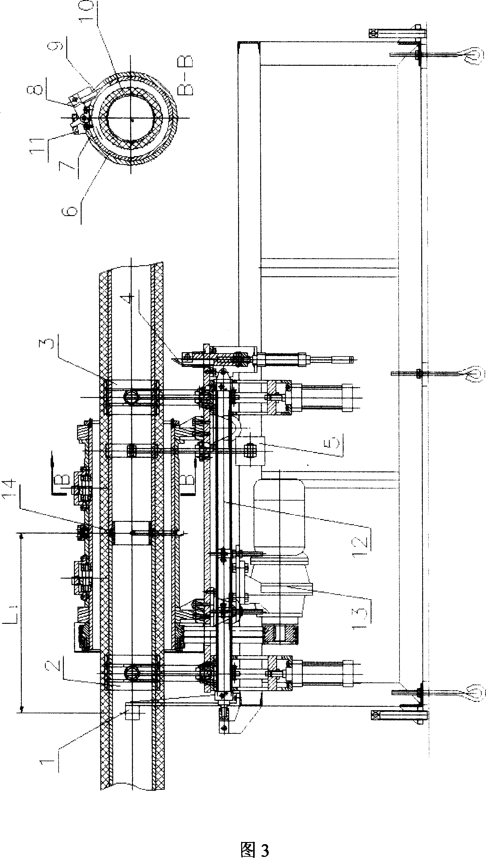
[0037] As shown in FIG. 2 to FIG. 9 , they are respectively state diagrams of the automatic foam jacket cutting machine according to the embodiment of the present invention in steps 1 to 8 of the cutting process. When the steel pipe joint covered by the foam jacket insulation layer in the previous process enters from one end of the equipment and passes through the steel pipe joint detector, a signal is sent from the detector. A series of actions are controlled by the microcomputer:

[0038] When the microcomputer detection data meet...


PUM


Abstract

The invention relates to an automat foam jack cutter and relative cutting method, wherein said device comprises a moving device parallel moving along the tube axial track with foam jack layer, a clamper for clamping the foam jack layer, a cutting device for cutting the foam jack layer, a detector for detecting the detector to tube, and a controller for controlling the cutting process. The invention has a feeding separating device with speed differential design and adjustable force. The invention uses micro computer control, with semi-automatic, full-automatic and hand-operated methods.

Description

technical field [0001] The invention relates to the technical field of pipe cutting, in particular to an online pipe foam jacket cutting device and a cutting method. Background technique [0002] In the previous "one-step" foam jacket forming operation line for steel pipes, the last process is to cut a small section (about 15cm) of the foam jacket layer at the connection of the steel pipe with a manual knife, and then the connection between the steel pipes can be withdrawn. The finished steel pipes with the foam jacket layer are removed from the line one by one and transported away; the most laborious process of manually cutting the foam jacket layer of the steel pipe is that it must be cut radially for at least three weeks , that is to say, it is necessary to insert the knife radially into the foam jacket layer and then forcefully rotate it to cut 360 degrees every week, so cutting for three rounds, and also to walk with the pipeline advancing on the line, which is very lab...

Claims


Application Information

Patent Timeline
IPC IPC(8): B26D5/20B26D7/02B26D7/24B26D7/27B26D7/26B26D7/06B26D7/32B26D1/56B26D1/04
Inventor 张景远邹汉中张国祯庄士奇
Owner 张景远
Learn More