Lamp assembly, discharge lamp and method for constructing such a lamp assembly

A technology for discharge lamps and lamp assemblies, applied in the directions of discharge lamps, discharge tubes, incandescent lamp parts, etc., can solve problems such as lamp cap and lamp holder damage, lamp assembly failure, rupture, etc.

Inactive Publication Date: 2007-05-09
KONINKLIJKE PHILIPS ELECTRONICS NV
View PDF0 Cites 0 Cited by
  • Summary
  • Abstract
  • Description
  • Claims
  • Application Information

AI Technical Summary

Problems solved by technology

Due to this significant temperature rise, usually both the lamp cap and spring will oxidize, leading to accelerated lamp (component) failure and thus a relatively shortened lamp component life
As a result of this oxidation, both the lamp cap and lamp holder are damaged
Furthermore, since certain parts of discharge lamps, such as the discharge vessel and the two pinches, are usually at least partly made of (quartz) glass, there is often a high risk of The shrinkage part of the glass will break relatively quickly, which also causes the lamp assembly to fail

Method used


Image

  • Lamp assembly, discharge lamp and method for constructing such a lamp assembly
  • Lamp assembly, discharge lamp and method for constructing such a lamp assembly
  • Lamp assembly, discharge lamp and method for constructing such a lamp assembly

Examples


Embodiment Construction

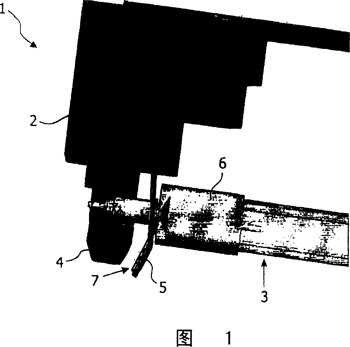
[0015] Figure 1 shows a perspective view of a part of a lamp assembly 1 according to the invention. The lamp assembly 1 comprises a lamp holder 2 and a discharge lamp 3 connected to said lamp holder 2 by two kinds of spring blades 4 and 5 . The first spring leaf 4 consists of two mutually cooperating spring leaves 4 (only one is shown), between which the lamp cap 6 of the discharge lamp 3 is mechanically clamped. The second leaf spring 5 has a slot 7 through which the lamp cap 6 extends. The second spring leaf 5 has a double function, the second spring leaf 7 is simultaneously used to mechanically fix the lamp cap 6 and to establish electrical contact between the lamp holder 2 and the discharge lamp 3 so as to be able to charge the discharge lamp 3 powered by. However, it has been found in practice that an (optimum) electrical contact can only be made if the lampholder 2 and the lamp 3 have ideal mutual dimensions at the same time. For example, if the length of the discharg...


PUM


Abstract

The invention relates to a lamp assembly, comprising: a discharge lamp provided with at least one electrically conductive lamp cap, and a discharge lamp holder provided with at least one electrically conductive biasing means for exerting a pressure upon said lamp cap for holding said discharge lamp in position. The invention also relates to a discharge lamp for use in such a lamp assembly. The invention further relates to a method for constructing such a lamp assembly.

Description

technical field [0001] The invention relates to a lamp assembly comprising: a discharge lamp having at least one electrically conductive lamp cap, and having at least one electrically conductive biasing means to apply pressure to said lamp cap to hold said discharge lamp in place discharge lamp holder. The invention also relates to a discharge lamp for use in such a lamp assembly. The invention also relates to a method of constructing such a lamp assembly. Background technique [0002] It is known in the prior art that discharge lamps, in particular high-intensity discharge (HID) lamps, can be clamped in lampholders by means of metal spring plates. The leaf spring thus exerts pressure on the metal cap which is part of the discharge lamp to hold the discharge lamp in place. In addition, the spring piece also has an electrical function, and electricity can be supplied to the discharge lamp through the metal spring piece. Usually these discharge lamps are double-ended and t...

Claims


Application Information

Patent Timeline
Patent Type & Authority Applications(China)
IPC IPC(8): H01J5/54H01R33/08F21V19/00F21Y101/00
CPCF21V19/0075
Inventor L·兰默兰特A·H·A·沙伦博格
Owner KONINKLIJKE PHILIPS ELECTRONICS NV
Why Eureka
Try Eureka