
Starting device for gaseous discharging lamp

A gas discharge lamp and starting device technology, which is applied in the use of gas discharge lamps, lighting devices, electric light sources, etc., can solve the problems of increasing circuit complexity and increasing the overall cost of ballasts, so as to save booster modules and reduce overall cost effect

Inactive Publication Date: 2007-05-09
KONINKLIJKE PHILIPS ELECTRONICS NV
View PDF0 Cites 2 Cited by
  • Summary
  • Abstract
  • Description
  • Claims
  • Application Information

AI Technical Summary

Problems solved by technology

[0005] In the above start-up mode, the DCBUS needs to be boosted, which not only increases the complexity of the circuit, but also puts forward higher requirements on the performance parameters of the electrical components of the entire circuit, for example, electrolytic capacitors or shocks that require higher withstand voltage parameters. Switching elements with higher wear voltage, etc., thus significantly increasing the overall cost of the ballast

Method used


Image

  • Starting device for gaseous discharging lamp
  • Starting device for gaseous discharging lamp
  • Starting device for gaseous discharging lamp

Examples


Embodiment Construction

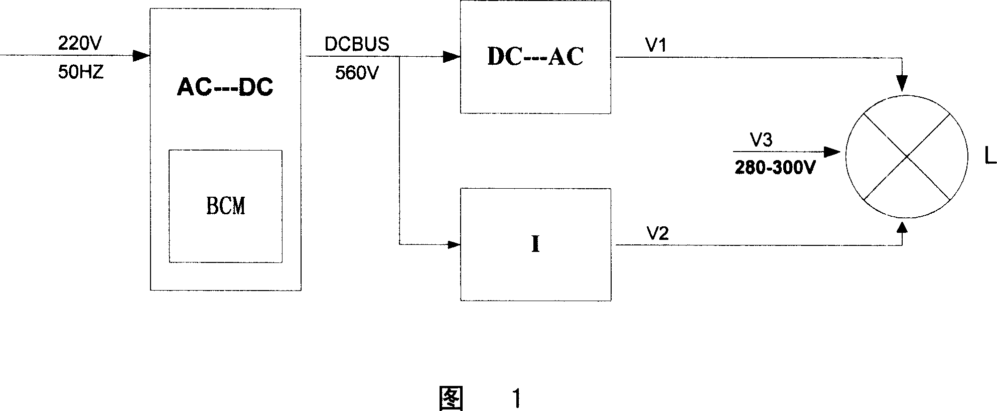
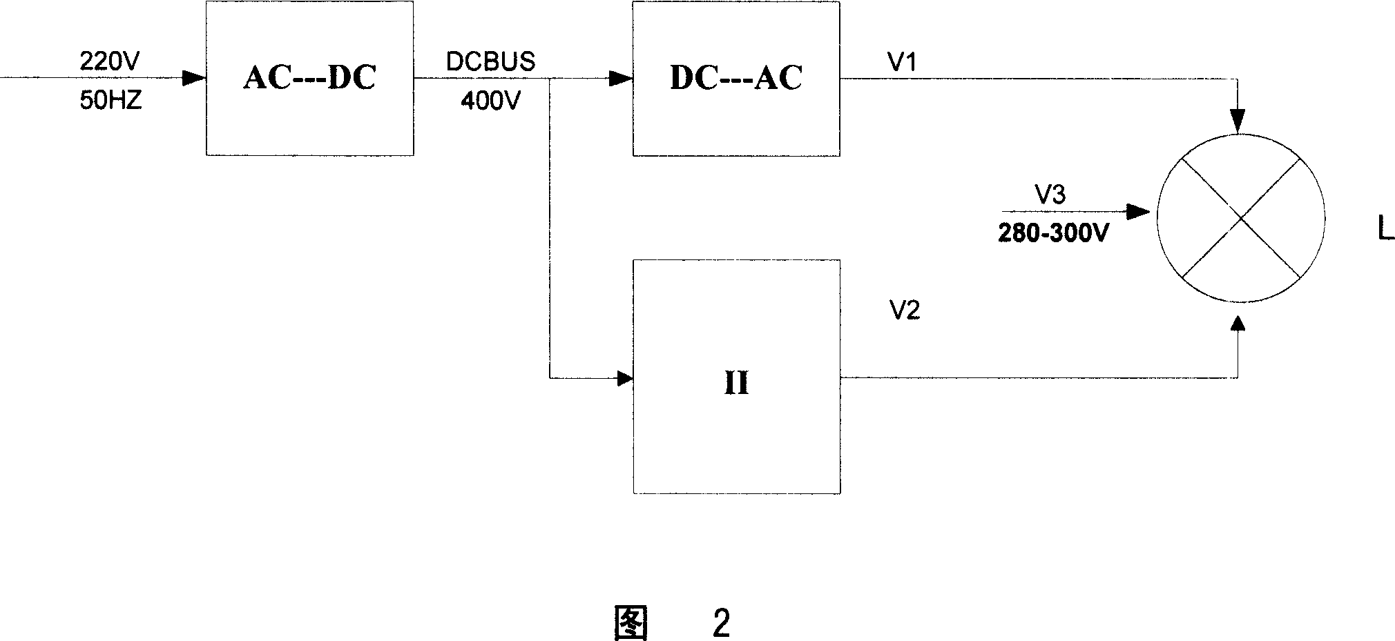
[0030] Fig. 2 is a functional block diagram of starting with the high intensity discharge lamp of the present invention. Compared with the prior art shown in Figure 1, after the improved start-up circuit is adopted, a lower DC bus (DCBUS) voltage can be used, such as a standard DC bus voltage of 400V, without further boosting of the DC bus DCBUS voltage . For example, after rectifying and converting the mains power to obtain the DC bus voltage of 400V, the AC voltage V1 can be obtained directly through an inverter circuit, and the effective value is 200V; Indicates) also outputs a voltage V2 with a certain effective value. The final open-circuit voltage V3 acting on the high-intensity gas discharge lamp will be formed by superimposing the voltage V1 directly output through the inverter circuit and the voltage V2 output through the starting circuit.

[0031] Here, our symbol || represents the effective value of a certain voltage. Since the output voltages V1 and V2 of the in...


PUM


Abstract

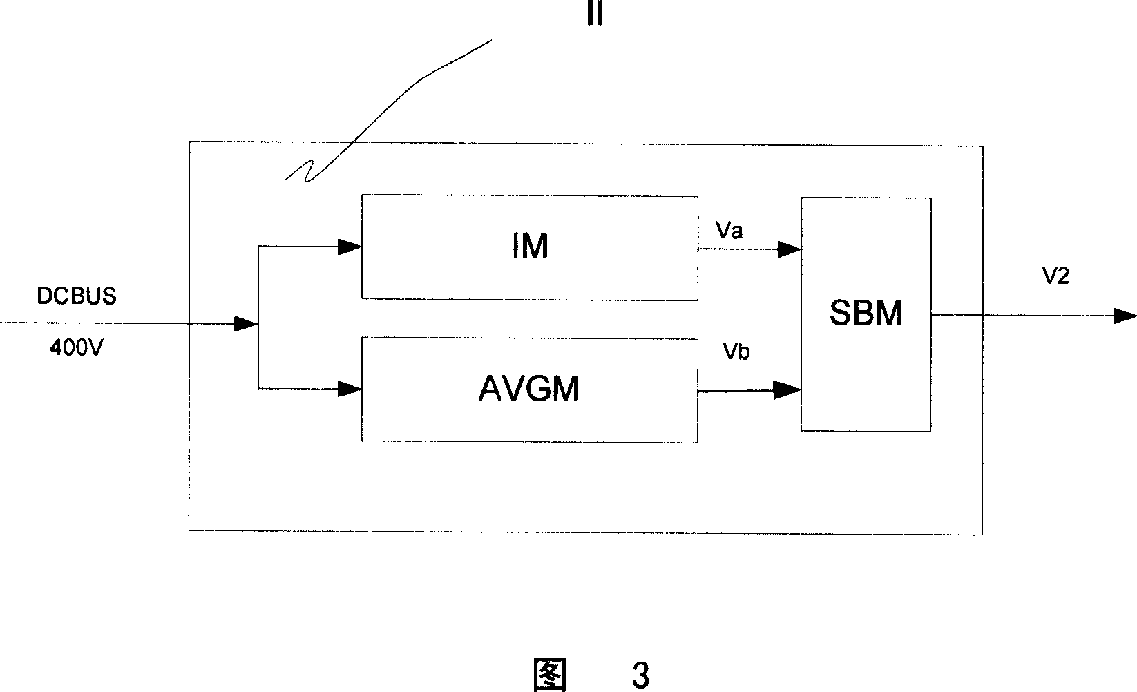
The invention is designed to be used in the ballast of high intensity gas-discharge lamp and comprises: a first module for generating first group of pulse voltage according to a low frequency driving signal; a second module for generating second group of pulse voltage according to a high frequency driving signal; a stacking and boosting module for stacking and boosting the first group of pulse voltage and second group of pulse voltage in order to generate a group of outputting voltage for breaking down the discharge lamp.

Description

technical field [0001] The invention relates to a starting device for a gas discharge lamp, in particular a starting device for a high intensity discharge lamp (HID) electronic ballast. Background technique [0002] During the start-up process of high-intensity discharge lamps (HID), not only the instantaneous high-voltage pulse ignition voltage needs to be generated at both ends of the arc tube, but also the electronic ballast needs to provide a higher effective value of the open circuit voltage (OCV) to provide sufficient Energy, so that the glow discharge is converted into arc discharge as soon as possible, and the start-up process is completed. The current common electronic ballast circuit structure generally includes a rectification and power factor correction circuit part (AC-DC), an inverter circuit part (DC-AC) and a starting circuit part (Ignitor, also known as a trigger). Through the rectification and power factor correction part, the mains voltage is converted in...

Claims


Application Information

Patent Timeline
Patent Type & Authority Applications(China)
IPC IPC(8): H05B41/288
CPCY02B20/204H05B41/2881Y02B20/00
Inventor 孙世光江春成刘忻
Owner KONINKLIJKE PHILIPS ELECTRONICS NV
Learn More