
Luminescence diode lighting module and lighting device

A technology of light-emitting diodes and lighting modules, applied in lighting devices, components of lighting devices, lighting and heating equipment, etc., can solve problems such as the decline in lighting quality of lighting devices, achieve the effect of suppressing color difference and improving lighting quality

Inactive Publication Date: 2007-05-09
TOSHIBA LIGHTING & TECH CORP
View PDF2 Cites 7 Cited by
  • Summary
  • Abstract
  • Description
  • Claims
  • Application Information

AI Technical Summary

Problems solved by technology

As a result, there is a problem that the lighting quality of the lighting device is significantly lowered due to chromatic aberration.

Method used


Image

  • Luminescence diode lighting module and lighting device
  • Luminescence diode lighting module and lighting device
  • Luminescence diode lighting module and lighting device

Examples


Embodiment

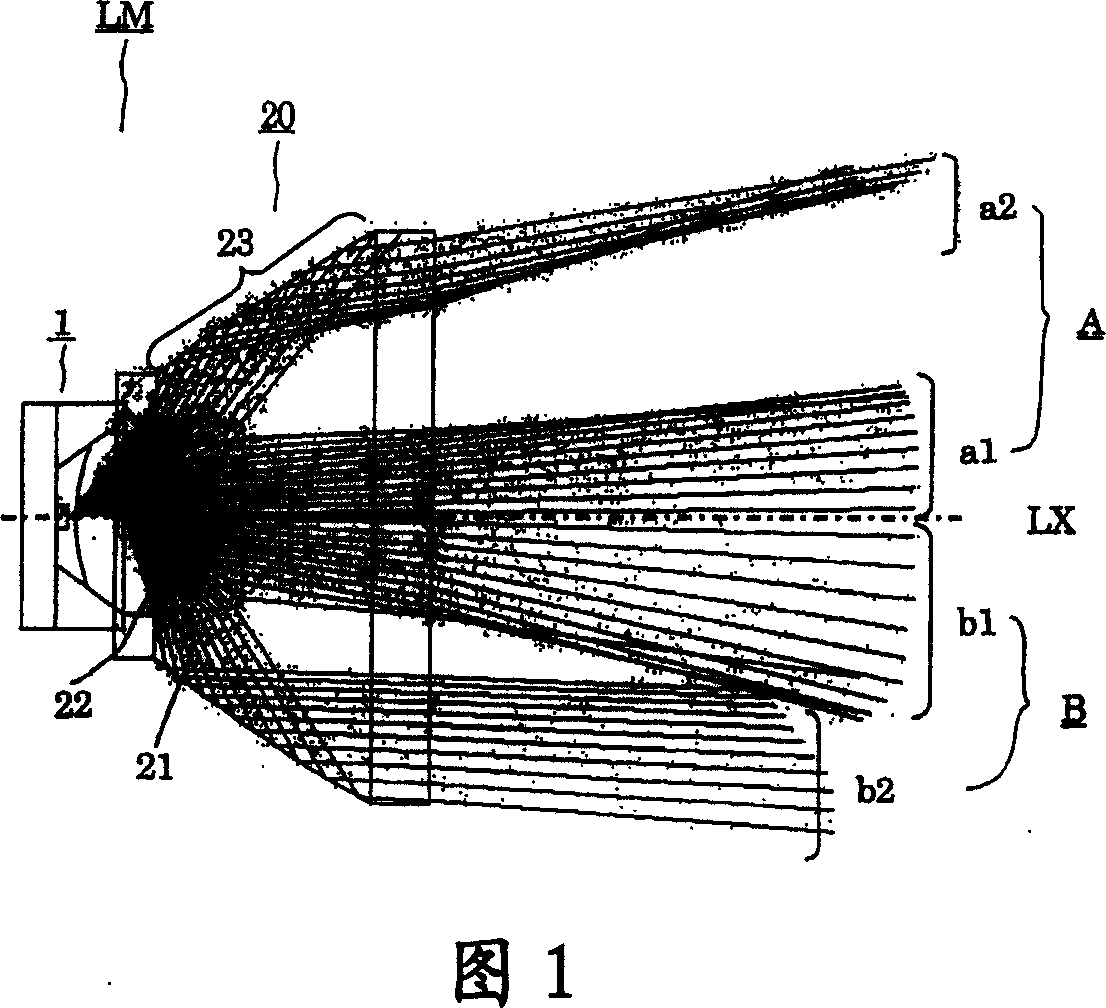
[0094] Fig. 7 is a graph showing the relationship between the output angle and the luminosity, wherein the relationship between the output angle and the luminosity is used to illustrate the distribution formed by the output light that is incident on the reflection part and then exits the direct light in the embodiment of this form. Light distribution characteristic A formed by direct light when the light peak is about 10°. In the figure, the horizontal axis represents the emission angle (°), and the vertical axis represents the luminosity (cd). In addition, it is shown separately: the graph shown by the long dashed line in the figure represents the photometric distribution of light a1, that is, the light distribution characteristic, and the graph shown by the short dashed line represents the photometric distribution of light a2, that is, the light distribution characteristic; The graph shown in FIG. 1 shows the light intensity distribution of light a1+a2, that is, the light di...


PUM


Abstract

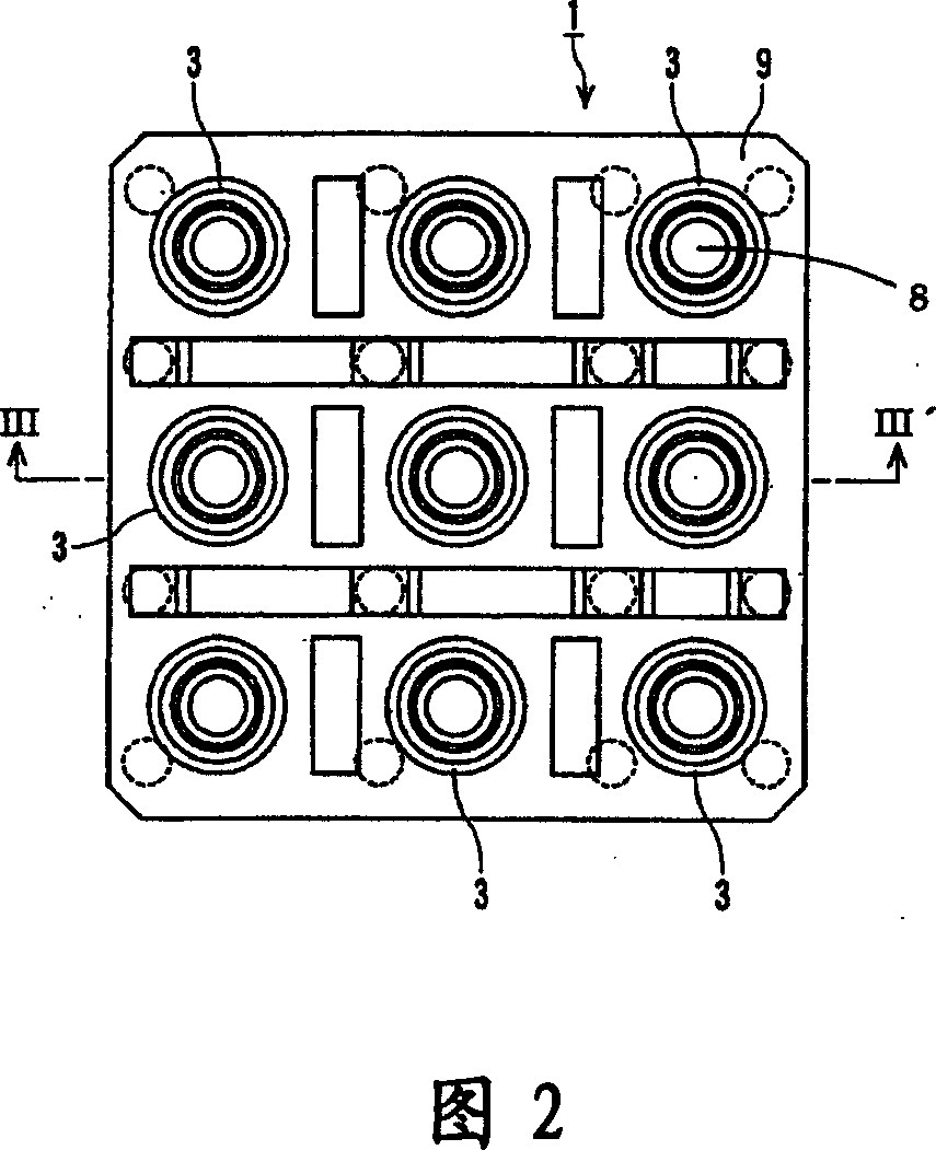
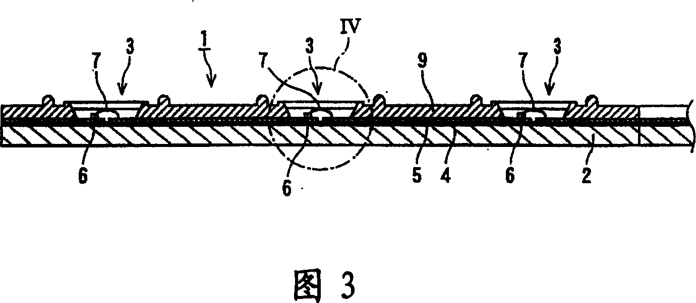
Luminescence diode lighting module and lighting device using same for improving lighting quality by inhibiting color difference generation is provided in this invention. A luminescence diode lighting module LM comprises a luminescence diode (1) and a lens (20), wherein, the luminescence diode (1) comprises a fluorescent substance layer (12) which is arranged in such a manner that the wavelength transformation is performed to part of emitting light from a luminescence diode chip (6) provided on a substrate (2); the lens (20) is arranged opposite to the luminescence diode (1) and has a convex lens part (21) with incident light mainly having small emission angle, and a reflecting part (23) arranged around the convex lens part with incident light mainly having big emission angle; and the first light distribution characteristic (A) is almost the same with the second light distribution characteristic (B), wherein the first light distribution characteristic (A) is formed by light emitted from the luminescence diode chip (6) and transmitted directly from the convex lens part (21) and reflecting part (23); the second light distribution characteristic (B) is formed by light emitted from the fluorescent substance layer (12) and transmitted from the convex lens part (21) and reflecting part (23).

Description

technical field [0001] The present invention relates to an improvement of a light emitting diode (diode) lighting module and a lighting device equipped therewith. Background technique [0002] There is known an illuminating device provided with: a first lens (lens) for focusing light radiated from a light emitting diode; and a second lens for focusing light emitted from the first lens into substantially parallel light (for example, refer to Patent Document 1). . [0003] In addition, there is known a spotting projector in which light-emitting diode lighting modules are arranged in a matrix. The light-emitting diode lighting module combines a convex lens part, a concave part, a reflector body, and an LED lamp. The convex lens The part corrects the traveling direction of the light emitted from the LED (light-emitting diode, light-emitting diode) lamp to the front; the concave part accommodates the LED lamp; It is a paraboloid (paraboloid) or a curved surface close to a parab...

Claims


Application Information

Patent Timeline
Patent Type & Authority Applications(China)
IPC IPC(8): F21S2/00F21V13/00F21V5/04F21V7/04H01L25/00H01L25/075H01L33/00F21K9/20
CPCH01L2224/48091
Inventor 小川光三吉信真之森山严与户田雅宏
Owner TOSHIBA LIGHTING & TECH CORP
Learn More