
Multifunctional down stream tee joint

A multi-functional, three-way technology, applied in water supply installations, indoor sanitary pipeline installations, buildings, etc., can solve the problems of increasing decoration costs, slowing down the flow rate, and affecting the appearance, so as to save decoration costs, reduce energy loss, and reduce flow rate many effects

Inactive Publication Date: 2007-05-09
陆正新
View PDF0 Cites 0 Cited by
  • Summary
  • Abstract
  • Description
  • Claims
  • Application Information

AI Technical Summary

Problems solved by technology

[0002] Existing buildings, especially the bathrooms of residential buildings, are equipped with sewage discharge devices. Although these sewage discharge devices meet the national standards, they must be installed with holes to place hanging pipes. Because the drainage branch pipelines of upper-floor residents must be placed Under the ceiling of the bathroom of the residents on the lower floor, the rough pipelines greatly affect the appearance. For this reason, ordinary users will hang the ceiling in the bathroom, which increases the decoration cost
The shape of the tee connector of the existing sewer pipeline is T-shaped. In actual use, this structure has no effect on the two coaxial interfaces, and the water flow will not be blocked. However, when the water flow of the third interface enters At this time, since the interface is perpendicular to the pipe wall, the water flow directly impacts on the pipe wall, the energy loss is large and the flow velocity is slowed down. When there is sediment in the water flow, it is easy to accumulate here and block the tee
In addition, if the ordinary downstream tee is installed in the drainage system on the same floor, because there is no upper connection, once the pipeline is blocked, the residents cannot unblock it by themselves, and because it is inside the floor, even professionals cannot solve it.

Method used


Image

  • Multifunctional down stream tee joint
  • Multifunctional down stream tee joint
  • Multifunctional down stream tee joint

Examples


Embodiment Construction

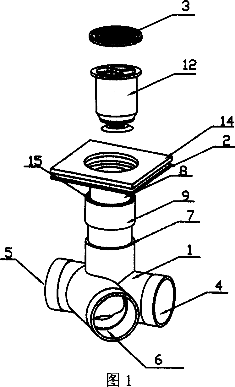
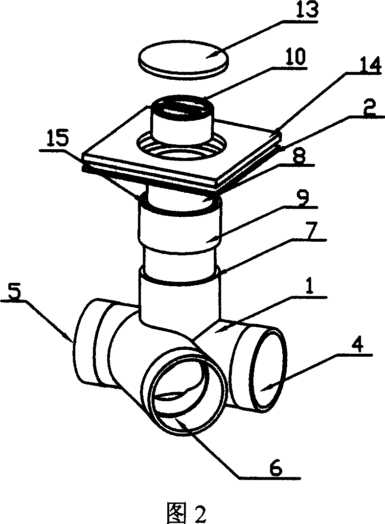
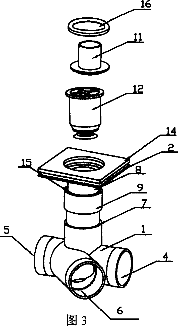
[0014] As shown in Figure 1, when used as a floor drain, the multi-functional downstream tee of the present invention includes a tubular body 1, a rectangular panel 2, a cover plate 3, a variable diameter joint 9 and a self-sealing floor drain 12; the tubular body 1 There are sewage inlet 4 and sewage outlet 5 at both ends of the axis, a second sewage inlet 6 is arranged obliquely on the horizontal side of the tubular body 1, an upwardly extending upper interface 7 is provided on the vertical side of the tubular body 1, and a panel 2 There is a lower interface 8 extending downwards. In order to adjust the inclination angle of the present invention and increase the caliber, a reducing joint 9 is provided between the upper interface 7 of the tubular body 1 and the lower interface 8 extending downwards of the panel, which is self-sealing The floor drain 12 is installed in the lower interface 8 extending downward of the panel 2 , and the mesh-shaped cover plate 3 covers the opening...


PUM


Abstract

The present invention discloses a kind of multifunctional consequent tee used in the co-floor sewage discharge system. It includes a tubular self-body, a panel and a cover plate. The described tubular self-body is characterized by that its two ends are respectively equipped with a sewage inlet and a sewage outlet, on the horizontal side surface of said tubular self-body a second sewage inlet is obliquely set, and the vertical side surface of said tubular self-body is equipped with an upwards-extended upper mouthpiece, said panel has a downwards-extended lower mouthpiece, said lower mouthpiece is inserted into said upper mouthpiece, and the opening of said cover plate is covered by that above-mentioned cover plate. Besides, said invention also provides the concrete operation method of said multifunctional consequent tee and its concrete application method.

Description

1. Technical field [0001] The invention relates to a tee connector used in the same-floor drainage system, in particular to a multifunctional downstream tee. 2. Background technology [0002] Existing buildings, especially the bathrooms of residential buildings, are equipped with sewage discharge devices. Although these sewage discharge devices meet the national standards, they must be installed with holes to place hanging pipes. Because the drainage branch pipelines of upper-floor residents must be placed Under the ceiling of the bathroom of the residents on the lower floor, the rough pipelines greatly affect the appearance. For this reason, ordinary users will hang the ceiling in the bathroom, which increases the decoration cost. The shape of the tee connector of the existing sewer pipeline is T-shaped. In actual use, this structure has no effect on the two coaxial interfaces, and the water flow will not be blocked. However, when the water flow of the third interface enter...

Claims


Application Information

Patent Timeline
Patent Type & Authority Applications(China)
IPC IPC(8): E03C1/12
Inventor 陆正新
Owner 陆正新
Learn More