
Automatic sheet feed mechanism

A paper-feeding and automatic technology, which is applied in the field of automatic paper-feeding mechanism, can solve the problems of paper pulling, difficult handling of paper picking/separating, multi-sheet feeding or paper jamming, and achieve the effect of improving reliability

Inactive Publication Date: 2007-05-09
LITE ON TECH CORP
View PDF3 Cites 8 Cited by
  • Summary
  • Abstract
  • Description
  • Claims
  • Application Information

AI Technical Summary

Problems solved by technology

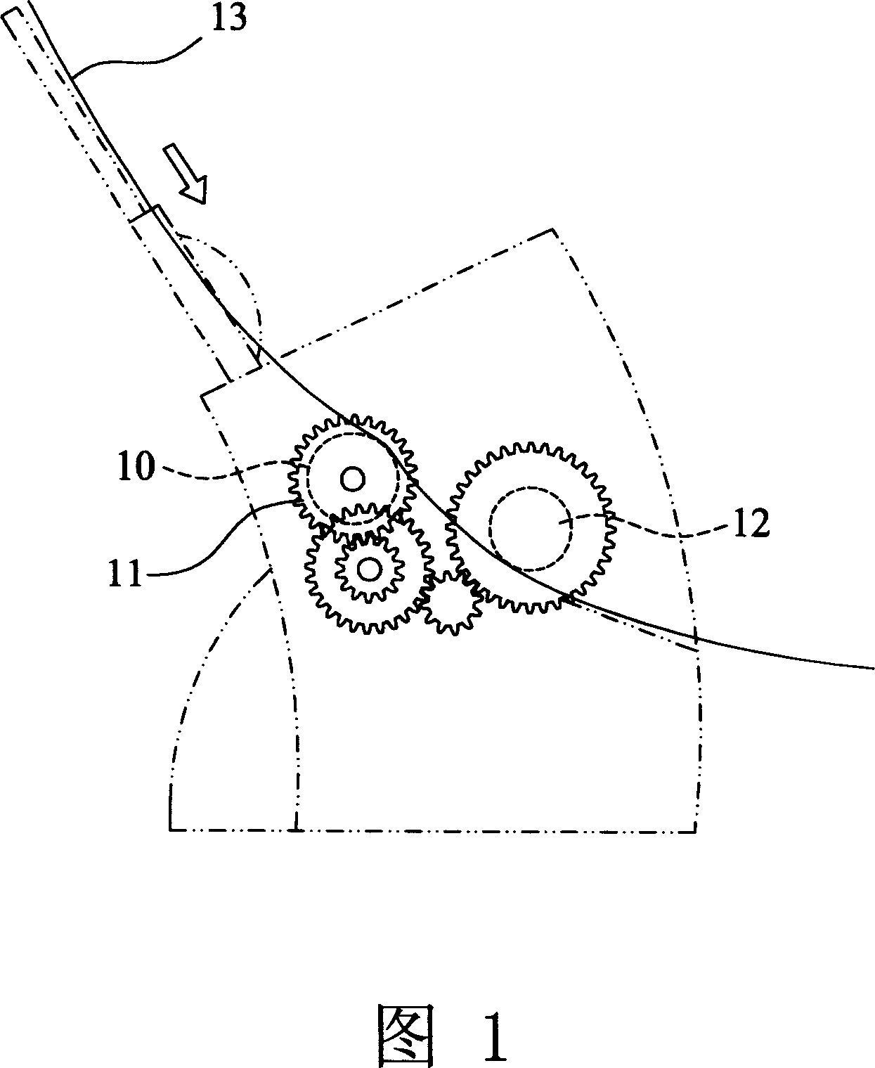
[0004] Although the above-mentioned patent has the function of paper picking / separating, there are still situations where the paper is pulled. In addition, the business machine often needs to process recycled paper, and the paper picking / separating of the recycled paper is even more difficult to handle.
[0005] In summary, although the paper fetching / separating mechanism disclosed above has the function of paper fetching / separating, its reliability is not high for recycled paper. Secondly, the current office machine has a high requirement for processing speed in practical use. Higher and higher, under high-speed conditions, the above-mentioned traditional design often has the phenomenon of multiple paper feeding or paper jamming

Method used


Image

  • Automatic sheet feed mechanism
  • Automatic sheet feed mechanism
  • Automatic sheet feed mechanism

Examples


Embodiment Construction

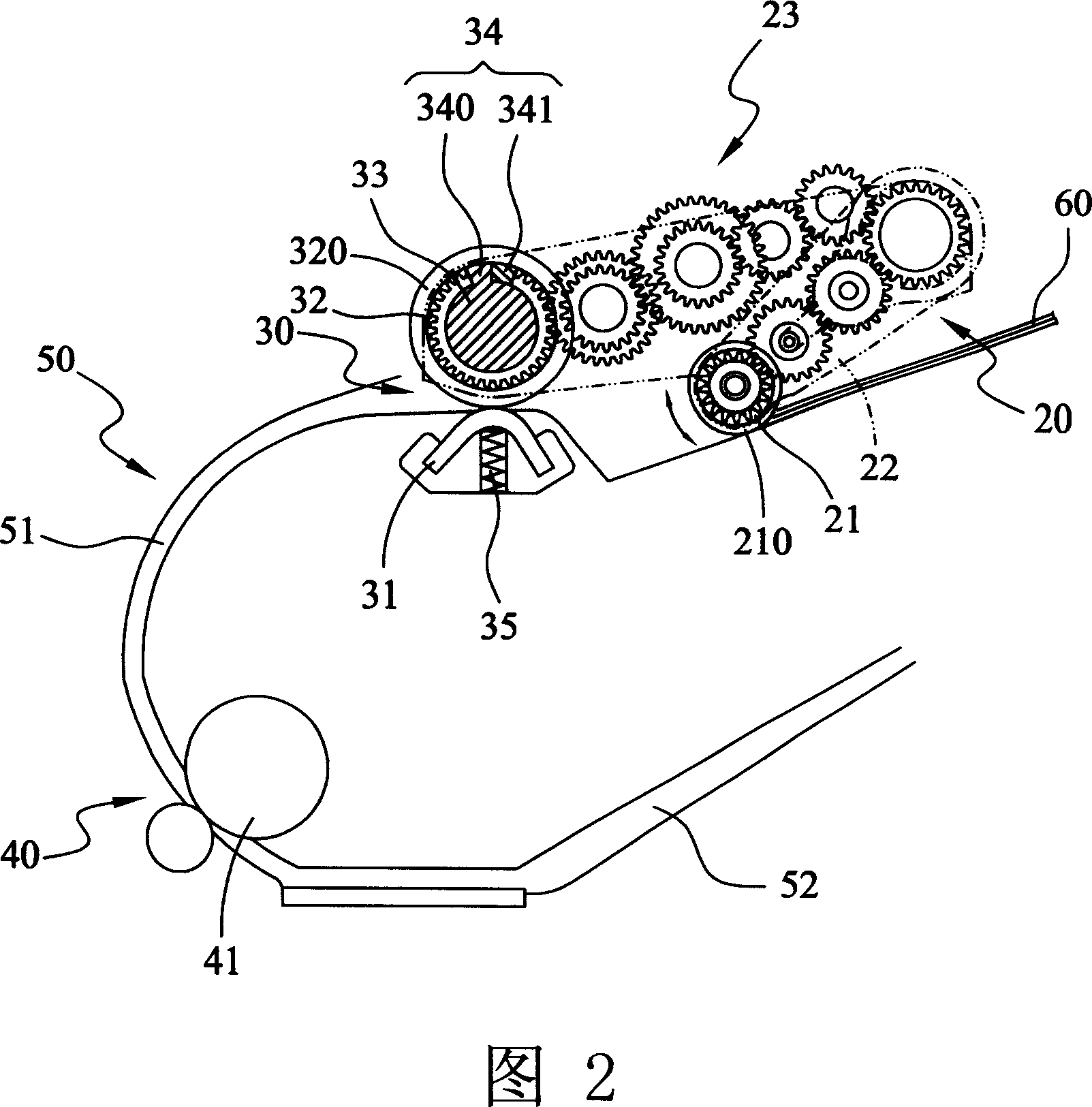
[0041] The automatic paper feeding mechanism disclosed in the present invention can be applied to fields such as multifunctional business machines, facsimile machines, copiers, scanners, etc. In the following specific embodiments of the present invention, it will be applied to scanners and multifunctional business The machine is described as the preferred embodiment of the present invention.

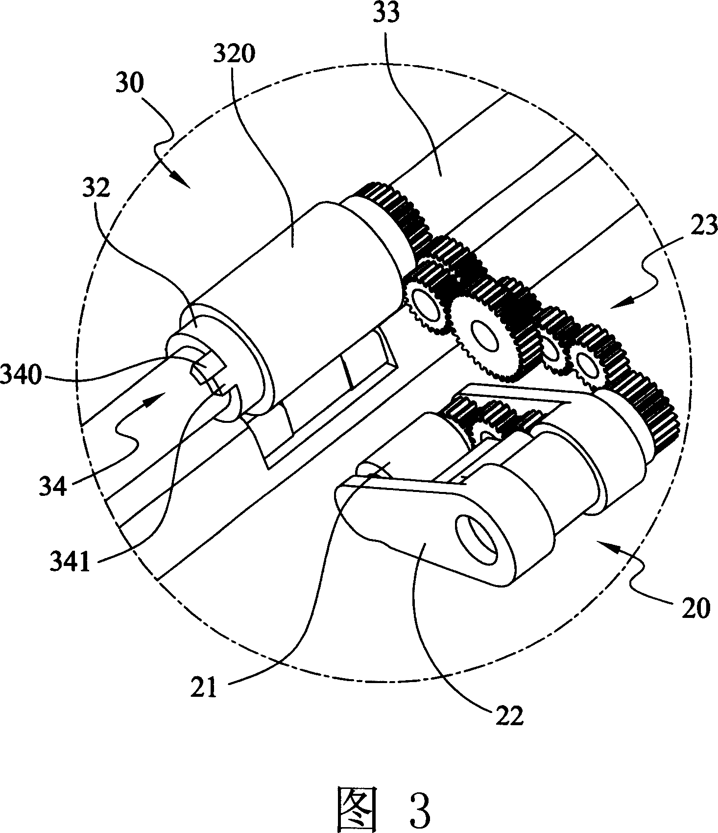
[0042] Please refer to Fig. 2, the present invention shown in the figure mainly comprises a paper-fetching assembly 20, a paper-separating assembly 30, a paper-feeding assembly 40, and a housing 50, forming a paper that can be moved when each assembly is running. 60 passes through the paper fetching assembly 20 , the paper separating assembly 30 , the paper feeding guide rail 51 formed by the housing 50 , and the paper feeding assembly 40 in sequence to reach the entrance 52 of the next operation.

[0043] Wherein, the above-mentioned paper picking assembly 20 includes a paper picking ro...


PUM


Abstract

An automatic paper feeding mechanism for multifunctional transaction appliance or scanner is composed of a paper getting module, a paper paging module and a paper running module. It has high reliability and speed.

Description

technical field [0001] The present invention relates to an automatic paper feeding mechanism, in particular to an automatic paper feeding mechanism applied to scanners, copiers, facsimile machines or multi-function business machines, which is used to separate stacked paper and transfer them into the business machine one by one , so that the transaction machine can proceed to the next operation. Background technique [0002] Please refer to Fig. 1, which is a known paper picking / feeding mechanism for a fax machine, which mainly includes a power gear 11, a paper picking roller 10 and a paper feeding roller 12, wherein the power gear 11 directly drives The paper roller 12 rotates, and there is a clutch member (not shown) formed by a spring between the power gear 11 and the paper pickup roller 10. At the same time, the speed of the paper delivery roller 12 is designed to be greater than that of the paper pickup roller 10. When this mechanism operates At this time, the power gea...

Claims


Application Information

Patent Timeline
Patent Type & Authority Applications(China)
IPC IPC(8): B65H3/06B65H3/50B65H5/06
Inventor 苏育仁
Owner LITE ON TECH CORP
Learn More