Magnetic rail brake device

一种磁轨制动器、制动电磁铁的技术,应用在制动元件与轨道相互作用的制动器、铁路制动系统、机动车等方向,能够解决磁短路、减小活节磁铁吸持力等问题

Inactive Publication Date: 2007-04-25
KNORR BREMSE SYST FUR SCHIENENFAHRZEUGE GMBH
View PDF1 Cites 14 Cited by
  • Summary
  • Abstract
  • Description
  • Claims
  • Application Information

AI Technical Summary

Problems solved by technology

Here, magnetic short circuits can occur due to gauge tie rods or steering cylinder flanges, which detrimentally reduce the holding force of the articulating magnets on the rails

Method used


Image

  • Magnetic rail brake device
  • Magnetic rail brake device

Examples


Embodiment Construction

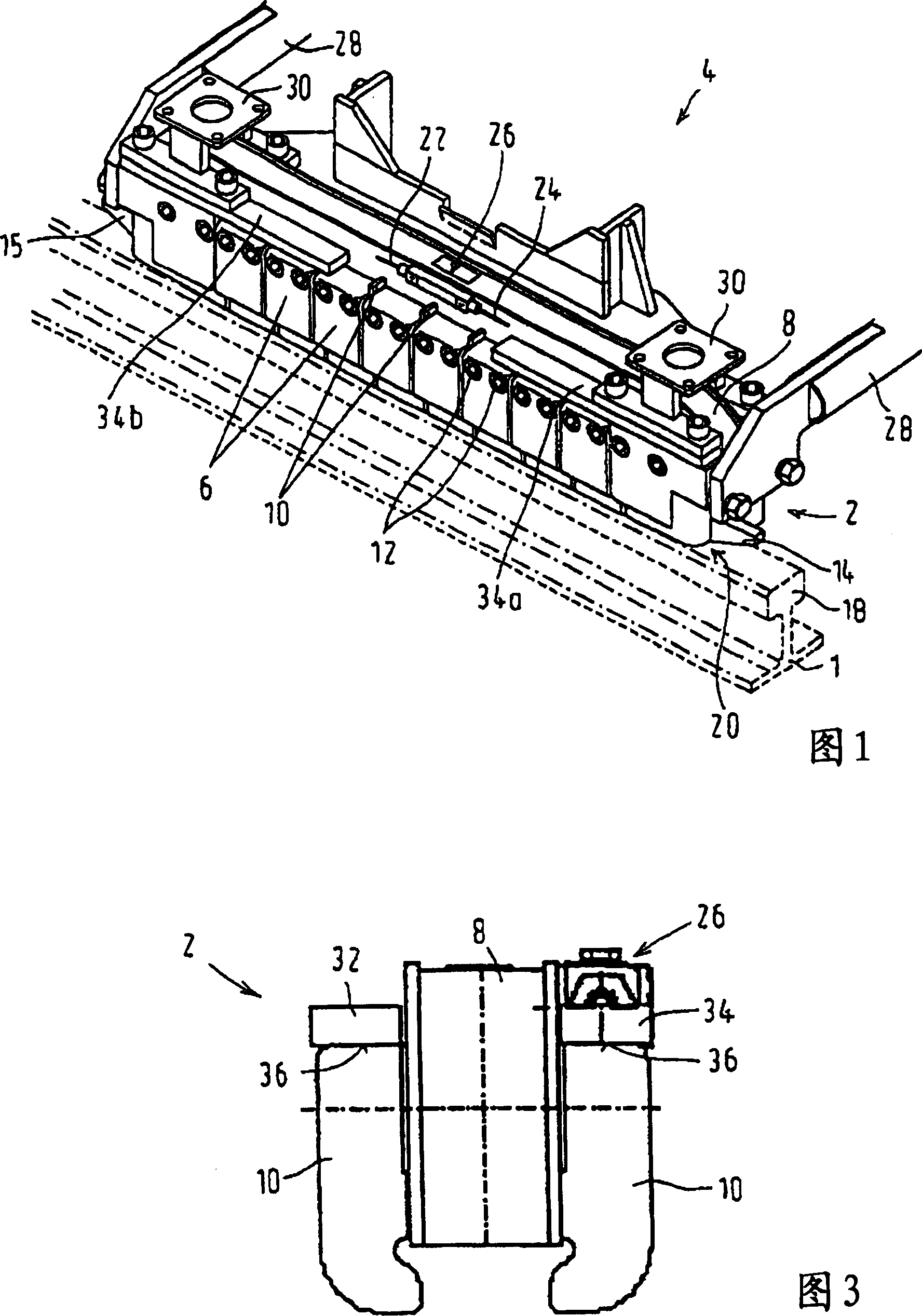
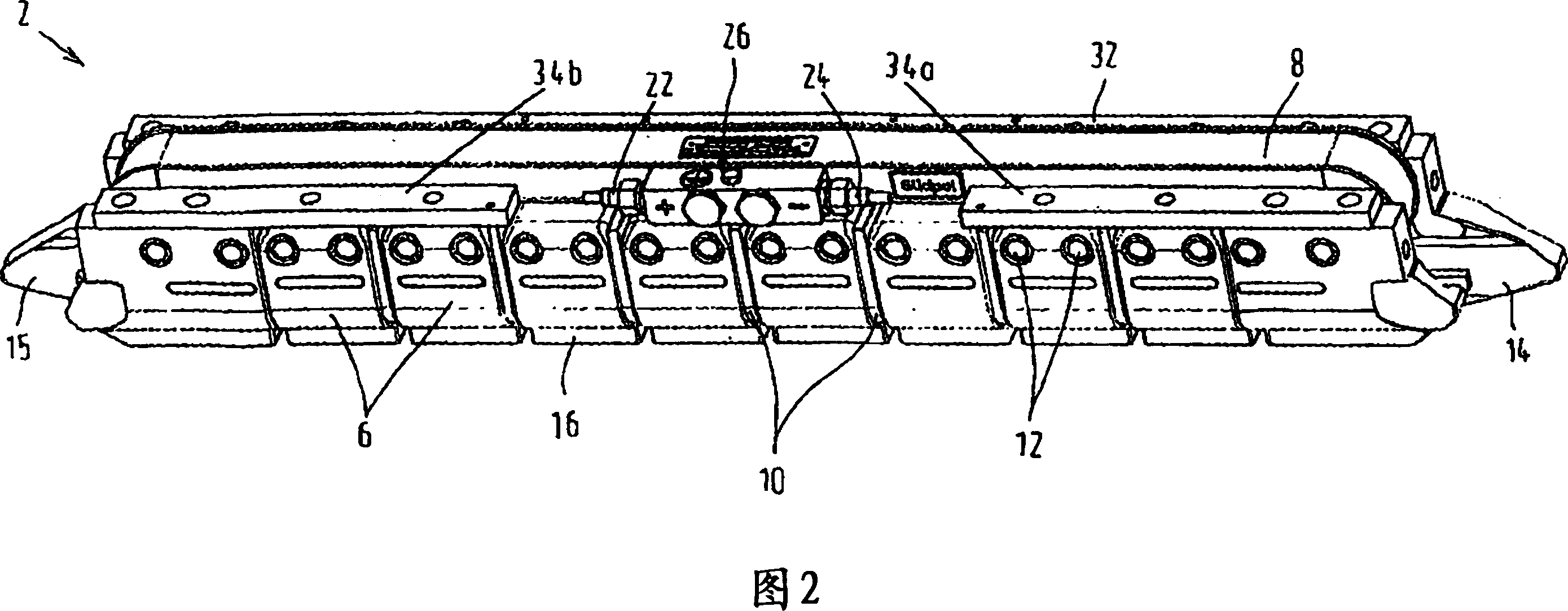
[0015] In order to be able to better adapt to the unevenness of the track 1, in the preferred embodiment of the brake electromagnet 2 of the magnetic track brake 4 shown in FIG. It is held on the field coil body 8 extending longitudinally along the rail 1 . This is preferably achieved in that the magnetic joint 6 is suspended symmetrically to the vertical center plane on the sides of the field coil body 8 facing away from each other, for example by means of screw connections 12 so that it can be swiveled to a limited extent or pivoted between the partitions 10 . cavity. The transmission of the braking force to the field coil form 8 is thus effected via the separator 10 . The terminals 14 , 15 are rigidly connected to the field coil body 8 and provide good guidance for the brake electromagnet 2 by means of the switch and track connections. The field coil body 8 , which contains a field coil not visible from the outside, thus supports the magnetic joints 6 , which form the mag...


PUM


Abstract

The invention relates to a magnetic rail brake device (4) of a railway vehicle, comprising at least one brake magnet (2) that is provided with a magnetic coil body (8) on which several magnetic members (6) are movably retained, and at least one fastening strip (32, 34) for fixing the brake magnet (2) to additional components of the magnetic rail brake device (4) such as anchor arms or flanges of actuation cylinders, said at least one fastening strip (32, 34) extending parallel to the longitudinal direction of the magnetic coil body (8) and being immediately connected thereto. According to the invention, the fastening strip (32, 34) is made of a diamagnetic or paramagnetic material, whereby the magnetic field is weakened or only slightly strengthened such that the magnetic leakage flux acting on the magnetic coil body (8) is significantly reduced, resulting in an advantageously great magnetic retention force.

Description

technical field [0001] The invention relates to a magnetic track brake of a railway rolling stock according to the preamble of claim 1, comprising at least one braking electromagnet comprising a plurality of magnetic magnets movably held thereon. The field coil body of the joint and at least one fastening strip running parallel to the length of the field coil body and directly connected thereto for fastening the braking electromagnet to other components of the magnetic track brake. Background technique [0002] A magnetic track brake is described, for example, in DE 101 11 685 A1. The main component of the electric magnetic track brake that generates the force is the brake electromagnet. In principle, it is an electromagnet consisting of an excitation coil extending in the direction of the track and a magnetic core forming a base or support similar to a horseshoe. The DC current flowing in the field coil creates the field voltage, which generates a magnetic flux in the mag...

Claims


Application Information

Patent Timeline
Patent Type & Authority Applications(China)
IPC IPC(8): B61H7/08
CPCB61H7/086B60L2200/26B61H7/08B61H7/00
Inventor H·莱曼H·科伊德尔L·施米德R·拉塔默S·哈斯
Owner KNORR BREMSE SYST FUR SCHIENENFAHRZEUGE GMBH
Why Eureka
Try Eureka