Branch protection negater circuit

A technology of protection switching and branch circuit, applied in the direction of electrical components, data exchange network, multiplexing communication, etc., can solve the problems of difficult product realization, difficult wiring, increased cost of single board and backplane, etc., to improve the quality of signal transmission , to ensure the integrity, product easy effect

Inactive Publication Date: 2007-04-18
HUAWEI TECH CO LTD
View PDF0 Cites 2 Cited by
  • Summary
  • Abstract
  • Description
  • Claims
  • Application Information

AI Technical Summary

Problems solved by technology

[0010] 1. The requirements for the single board (working board or protection board) with the selection switch to select the bus are very high. Once there is a problem with the board, it cannot be switched to the backup board, so the board-level protection scheme is unreliable
[0011] 2. The outlet density of the single board with the selection switch to select the bus is doubled, and one more connector is used, which brings certain difficulties to the wiring on the board, and the product is difficult to realize, and the cost of the backplane of the single board is increased
[0012] As the integration density of the system increases and the processing capacity becomes stronger, it is required to improve the reliability of the system, which makes the design requirements for the branch switching protection circuit more complicated. The previous circuit protection scheme cannot guarantee the reliability of the new interconnection scheme. Requirements, with the increasing rate of the signal to be protected (such as the FE circuit protection scheme) and the increase of the signal transmission distance, the signal routing has shown the characteristics of the transmission line, that is, the signal transmission system is already a distributed system, not The lumped system cannot be solved by using the protection scheme of the prior art 1, that is, the lumped scheme; while the protection scheme of the prior art 2, board-level protection is unreliable, and product realization is relatively difficult

Method used


Image

  • Branch protection negater circuit
  • Branch protection negater circuit
  • Branch protection negater circuit

Examples


Embodiment Construction

[0031] Further elaboration below in conjunction with accompanying drawing and embodiment:

[0032] In order to realize the higher-speed signal circuit and the branch protection switching function of the distributed system, and ensure the integrity of signal transmission, the embodiments of the present invention provide three solutions:

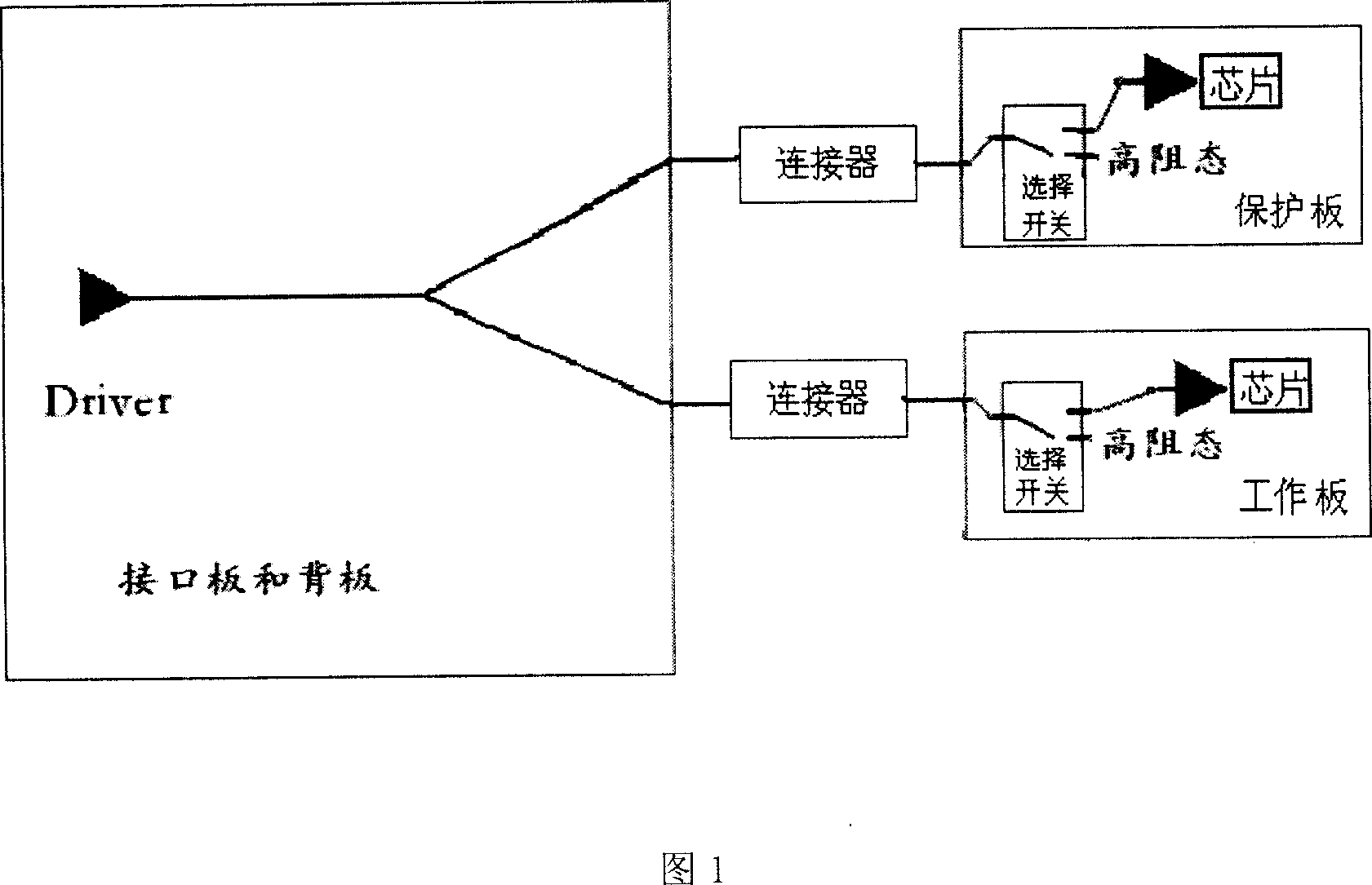
[0033]6 is a block diagram of a branch switching protection circuit according to an embodiment of the present invention. The branch protection switching (TPS) circuit includes an interface board and a backplane part, two impedance matching networks, a working board and a protection board, and the interface board and the backplane part are respectively connected with the working board and the protection board through the connector. connected to the first end of the selection switch on the protection board to form a working channel and a protection channel, the second end of the selection switch on the working board is connected to the processin...


PUM


Abstract

The invention discloses a branch protection switching circuit, relating to a network equipment protection circuit. And the branch protection switching circuit comprises driving end, at least a working plate and at least a protection plate, where the working plate and the protection plate are equipped with switch and processing chip, respectively, the driving end is branched into at least two branches which are connected through the switch with the processing chip; and also comprises at least two impedance matching networks whose first ends are connected to the said branches, respectively and whose second ends are connected to power supply VCC or ground. And it can improve signal transmission quality of interconnected systems with longer branched traces, and implement reliable protection for the interconnected systems.

Description

[technical field] [0001] The invention relates to a protection circuit of network equipment, in particular to a branch protection switching circuit. [Background technique] [0002] There is a 1:N protection mode for the design of branch protection switching circuits, where N=1, 2, 3..., which means that one protection board can protect N working boards, but at a certain moment, it can only protect N A working board for effective protection. For example, E1 / T1 or E3 / T3 signal circuit protection design in SDH (synchronous digital series, European standard in transmission equipment) or Sonet (synchronous optical network, North American standard in transmission equipment), among them, E1 / E3: PDH ( Quasi-synchronous digital series) European standard in the standard interface, T1 / T3: It is the North American standard in the PDH standard interface. For E1 / T1 signals with low signal transmission rate, N can be larger (greater than 3 or more), and for E3 / T3 signals with high signal...

Claims


Application Information

Patent Timeline
Patent Type & Authority Applications(China)
IPC IPC(8): H04L12/24H04J3/08
Inventor 邓治高
Owner HUAWEI TECH CO LTD
Why Eureka
Try Eureka