Method for making generator and generator
A manufacturing method and generator technology, which are applied in the manufacture of motor generators, synchronous motors with stationary armatures and rotating magnets, electrical components, etc., can solve the problems of low electromechanical energy conversion efficiency of generators and reduce the switching frequency. Effect
- Summary
- Abstract
- Description
- Claims
- Application Information
AI Technical Summary
Problems solved by technology
Method used
Image

Examples
Embodiment 1
[0036] Embodiment 1. An electric generator and its manufacturing method. As shown in FIG. 5 , it is a schematic structural diagram of the partial improvement of the electric generator shown in FIG. 1 . An improved method is to fill up the slot 5 with the magnetically permeable block 13 . Other structures are exactly the same as the existing structure shown in Fig. 1 . FIG. 6 shows the situation that the new wire package magnetic force lines 16 after the wire package magnetic force lines 15 are shielded and guided by the wedge block 13 are squeezed and deformed. Fig. 7 shows that the magnetic force lines 16 of the new wire-wrap magnetic field guided by the wedge block 13 and the magnetic force lines 14 of the rotating magnetic field will interfere with each other outside the wire-wrap region, because the magnetic force lines 14 of the rotating magnetic field 1 have not been completely restrained and are still There is room for further improvement.
[0037] It should be noted ...
Embodiment 2
[0038] Embodiment 2 Another generator, as shown in FIG. 8 , is a schematic diagram of a partial structure of the generator shown in FIG. 5 after further improvement. The improvement is that: the upper and lower sides of the ring-shaped permanent magnet 1 and the back 103 are fixed with a shielding ring 6, and the shielding ring 6 is a double "L" structure, wherein the upper and lower sides of the permanent magnet 1 (101, 102) There is a gap 104 between it and the shielding ring 6 , which is used to constrain the cyclic amplitude of the magnetic force lines of the rotating magnetic field, so that the magnetic force lines of the rotating magnetic field are lower than the thickness of the iron core 2 when they enter the iron core 2 . The shielding ring 6 must be made of magnetically permeable materials such as iron or ferrite. Figure 9 provides a schematic diagram of the distribution of the magnetic lines of force after the shielding ring 6 is set. Compared with Figure 7, the lin...
Embodiment 3
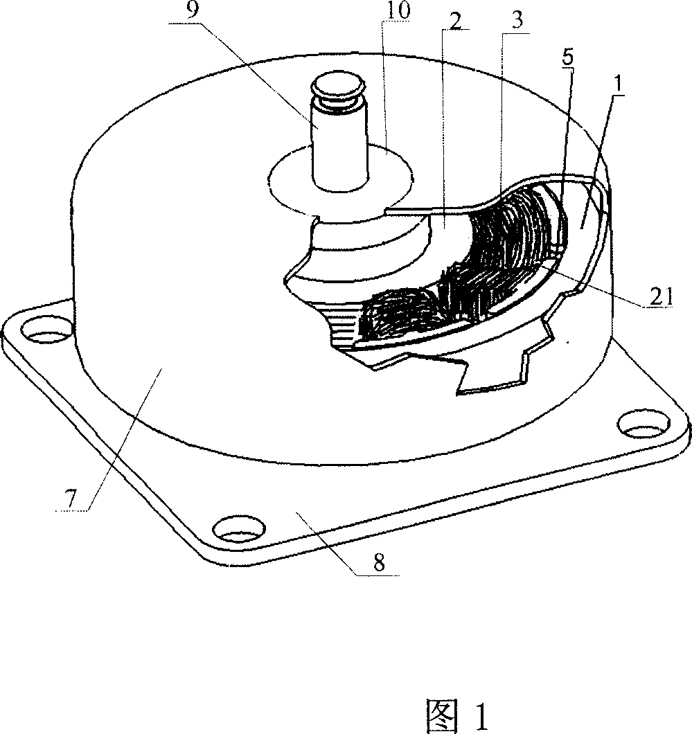
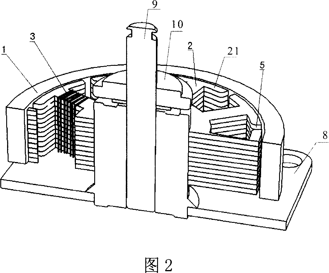
[0065] Embodiment 3, another kind of improved generator, as shown in Figure 12: including casing 7, main shaft 9, permanent magnet 1, shielding ring 6, iron core claw 2, iron core 4, bottom plate 8, main shaft 9 are contained in The main sleeve 10 and the main sleeve 10 are equipped with an iron core 4; the iron core 4 is provided with a plurality of slots 19, and each individually wound wire package 3 is installed on the iron core 4 through the corresponding slot 19, and the iron core 4 The core claw 2 is formed by overlapping a plurality of iron core claw pieces 201 , the iron core pole piece 2 is equipped with a wire roller 11 , and the wire package 3 is individually wound in the wire roller 11 . Each iron core claw piece 201 is inserted through the wire package 3 in the direction of the arrow * in FIG. The iron core pole pieces 201 and the inner iron core 4 are engaged with each other. Only a tiny seam 12 remains between the inserted iron core claws 2 . The casing 7 and ...
PUM
| Property | Measurement | Unit |
|---|---|---|
| Diameter | aaaaa | aaaaa |
Abstract
Description
Claims
Application Information
 - R&D
- Intellectual Property
- Life Sciences
- Materials
- Tech Scout
- Unparalleled Data Quality
- Higher Quality Content
- 60% Fewer Hallucinations
Browse by: Latest US Patents, China's latest patents, Technical Efficacy Thesaurus, Application Domain, Technology Topic, Popular Technical Reports.
© 2025 PatSnap. All rights reserved.Legal|Privacy policy|Modern Slavery Act Transparency Statement|Sitemap|About US| Contact US: help@patsnap.com