Eureka AIR delivers breakthrough ideas for toughest innovation challenges, trusted by R&D personnel around the world.

Coating drier with regulating air flow path function

A drying device and air flow path technology, applied in photoplate making process coating equipment, optics, instruments, etc., can solve the problems affecting production efficiency and uneven film thickness, avoiding uneven film thickness, improving quality, and improving airflow. effect of path

Active Publication Date: 2007-04-11
AU OPTRONICS CORP
View PDF0 Cites 7 Cited by
  • Summary
  • Abstract
  • Description
  • Claims
  • Application Information

AI Technical Summary

Problems solved by technology

However, the structural design of the existing coating device will make the path of the air flow close to the surface of the photoresist layer when the solvent is pumped out, so the surface of the photoresist layer is easily damaged by the air flow during the rough pumping action. The problem of different film thickness
The display defect caused by the different film thickness of liquid crystal display is generally called in the industry as display defect caused by vacuum drying (VCD-vacuum chamber drying mura), and the existing method to solve this problem is to extend the time of the fine pumping action to solve it , but this will seriously affect the production efficiency

Method used


Image

  • Coating drier with regulating air flow path function

Examples


Embodiment Construction

[0016] The following are detailed descriptions and accompanying drawings of the present invention. However, the accompanying drawings are only for reference and auxiliary description, and are not intended to limit the present invention.

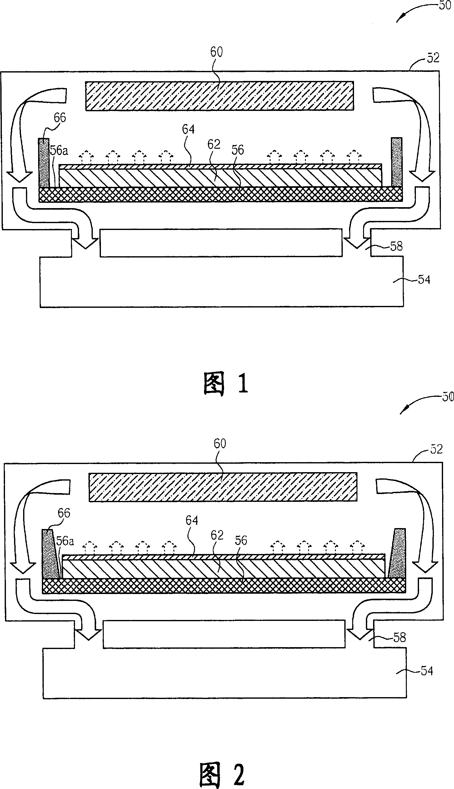
[0017] Please refer to Fig. 1, Fig. 1 is a schematic diagram of a coating and drying device with the function of adjusting the airflow path of a preferred embodiment of the present invention, wherein the following embodiment is a slit type (slit) for making color filters ) coating device as an example to illustrate the characteristics of the present invention, but the application of the present invention is not limited thereto, but can be applied to other such as rotary coating device or vacuum drying device, or for making non-color filter Photoresist layers and other coating material layers, etc. As shown in FIG. 1 , the coating device 50 of this embodiment includes a reaction chamber 52 , a vacuum system (such as a vacuum pump) 54 , and a ...


PUM


Abstract

The invention discloses a coating drying equipment with function of adjusting the flow path, including: a reaction chamber, a vacuum system that connects the chamber to extract gas in the chamber, a loading platform that is set in the chamber and includes a loading surface to load a base plate, and a baffle plate structure that is set on the loading surface surrounding the base plate, and its height is more than the thickness of the base plate. Accordingly, when extracting the gas in the chamber, the vacuum system can uniformly extract the solvent in the photoresist layer.

Description

technical field [0001] The present invention relates to a coating device, in particular to a coating and drying device that utilizes a baffle structure disposed on a loading platform to adjust an airflow path. Background technique [0002] Liquid crystal displays have become the mainstream products in the monitor and thin TV market due to their advantages of thinness, lightness, shortness and power saving. For liquid crystal displays, color filters are one of the most important key components. Only through the filtering effect of color filters can liquid crystal displays display brightly colored images. [0003] As the specifications and sizes of liquid crystal displays continue to increase, the requirements for the characteristics of color filters, such as heat resistance, are also increasing. In terms of current technology, the color filters produced by the pigment dispersion method can better meet the requirements. The demand at the present stage has become a more common...

Claims


Application Information

Patent Timeline
Patent Type & Authority Applications(China)
IPC IPC(8): G03F7/16G02B5/23
Inventor 陈嘉欣林彦伯林信志
Owner AU OPTRONICS CORP
Why Eureka
Eureka Blog
Learn More